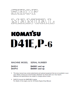
Komatsu D41E-6, D41P-6 Dozer Service Manual
Product Overview
The Komatsu D41E-6, D41P-6 Dozer Service Manual is designed to aid technicians in improving repair quality by providing a comprehensive understanding of the dozeru2019s components and repair procedures. This manual is an essential resource for service workshops, offering critical technical information and structured guidance on various maintenance tasks.
Key Features
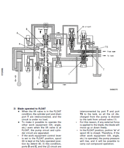
- Structure and Function: Detailed explanation of the structure and functionality of each component, vital for troubleshooting and understanding component interactions.
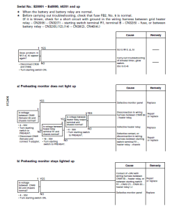
- Testing and Adjusting: Guidance on pre- and post-repair checks, as well as necessary adjustments. Includes troubleshooting charts that identify causes of common problems.
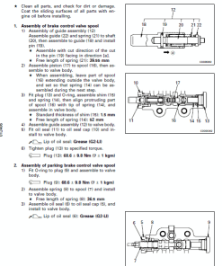
- Disassembly and Assembly: Step-by-step instructions on the order of operations for removal, installation, disassembly, and reassembly of parts, with safety precautions.
- Maintenance Standards: Information on inspection standards for disassembled components to ensure high-quality maintenance and repair.
Benefits
- Enhances repair quality by providing detailed instructions and technical detail.
- Improves efficiency and accuracy in troubleshooting and repair work.
- Facilitates better understanding of equipment, leading to optimal performance and longevity.
Usage Recommendations
- Ensure thorough understanding of the manual contents for effective use in service workshops.
- Utilize the manual as a reference during both regular maintenance and complex repair procedures.
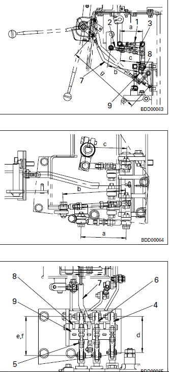
Adjusting Work Equipment Control Linkage and Safety Lever Linkage
To ensure proper operation and safety of the Komatsu Dozer, follow these adjustments meticulously:
- Adjusting Rod at Control Lever End:
- Lift Spool Rod: Set the distance between pins “a” to 96 mm.
- Tilt Spool Rod: Set the distance between pins “b” to 145 mm.
- Angle Spool Rod: Set the distance between pins “c” to 91 mm.
- Adjusting Rod at Spool End:
- Lift Spool Rod: Set the distance between pins “d” to 98 mm.
- Tilt Spool Rod: Set the distance between pins “e” to 104.6 mm.
- Angle Spool Rod: Set the distance between pins “f” to 104.6 mm.
- Adjusting Safety Lever Rod:
- Safety Lever: Set the distance between pins “g” to 345.9 mm. Ensure the safety lever is in the LOCK position and verify that pin (8) enters plate (9).
Only logged in customers who have purchased this product may leave a review.
Related products
$33.00
$34.00





Reviews
There are no reviews yet.