Case 750L, 850L Crawler Dozer Service Manual
$34.00
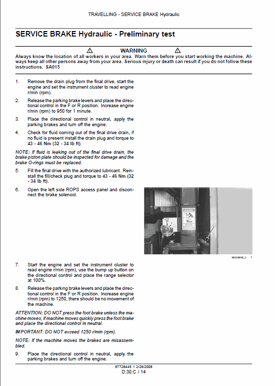
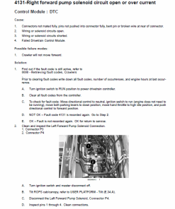
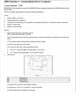
Manual Included: Comprehensive service manual with 1516 pages.
Specifications:
Brand: New Holland
Model: 750L, 850L
Type: Dozer
Manuals Available: Service Manual
Publication Number: 87728445 (March 2008)
Language: English
Format: PDF
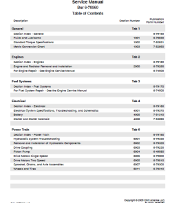
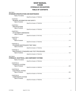
Table of Contents for Hydraulic and Electrical Systems Manual
Product Overview
This comprehensive manual provides detailed information on the various systems and components of the equipment, focusing primarily on hydraulic and electrical schematics. The guide is designed for professionals seeking in-depth knowledge to maintain and repair machinery effectively.
Contents
- Introduction
- Distribution Systems
- Power Production
- Power Train
- Traveling
- Body and Structure
- Tool Positioning
- Working Arm
- Tools and Couples
- Hydraulic Schematics
- Electrical Schematics
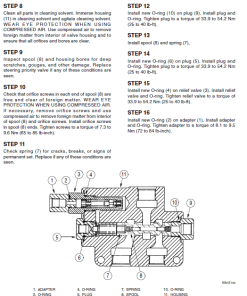
Manual Extract: Relief Valve Pressure Setting
Follow these steps to adjust the relief valve pressure setting to ensure optimal performance:
- Remove the hex cap and spring from the top of the circuit relief valve.
- Inspect the plunger for any damaged or worn parts or seals. Repair as necessary.
- Add or remove shims to adjust the pressure setting. Each shim measures 0.254 mm (0.010 in) and alters the pressure by 3.4 to 10.3 bar (50 to 150 psi).
- Reinstall the spring and hex cap on the circuit relief valve.
- Install the circuit relief valve back into the equipment control valve and perform the pressure test according to segment A.12.A.
- Make further adjustments to the valve, if necessary.
- Once the pressure setting is correct, disconnect the hand pump and reconnect the hydraulic line.
Key Benefits
- Comprehensive Details: Provides complete insights into both hydraulic and electrical systems.
- Step-by-Step Guidance: Detailed instructions ensure accurate maintenance and adjustment.
- Professional Standard: Ideal for technicians and engineers looking to master equipment repair.
Usage Recommendations
- Ensure all adjustments and repairs are performed by qualified personnel to maintain safety and equipment integrity.
- Regularly check and calibrate pressure settings for optimal performance.
- Consult the manual sections relevant to each procedure for comprehensive support.
Only logged in customers who have purchased this product may leave a review.
Related products
$35.00
$33.00
$34.00
$34.00
$34.00
$34.00
$34.00
$34.00


Reviews
There are no reviews yet.