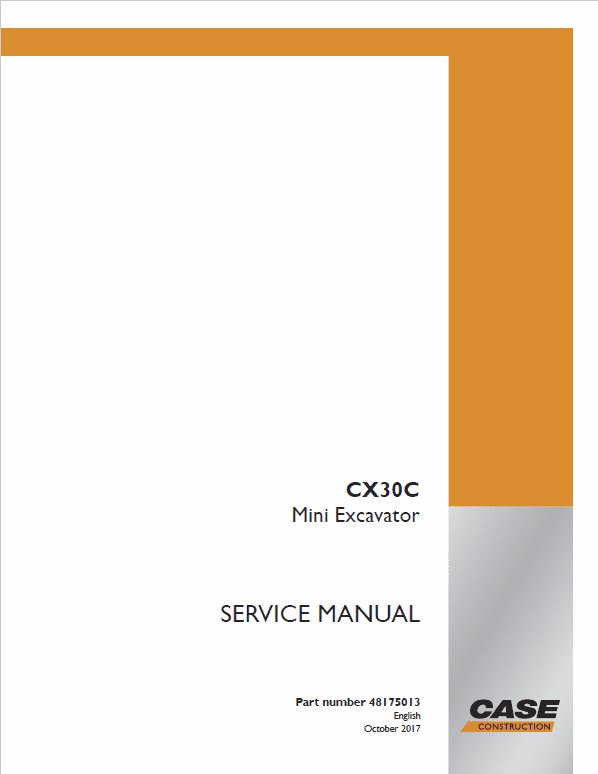
Case CX30C Mini Excavator Service Manual
$36.00
The comprehensive service manual for the New Holland CX30C Mini Excavator is an essential resource, featuring 1375 pages of detailed information.
Brand: New Holland
Model: CX30C
Type: Mini Excavator
Manual Includes: Service Manual
Publication Number: 48175013 (Oct 2017)
Language: English
Format: PDF
Comprehensive Guide to Mechanical Systems and Valve Maintenance
Product Overview
This manual provides detailed instructions and schematics essential for the maintenance and operation of various mechanical systems. It is an invaluable resource for understanding engine components, hydraulic systems, and much more. Whether you are a professional technician or an enthusiastic DIYer, this guide is designed to ensure your technical proficiency and success in handling intricate machinery.
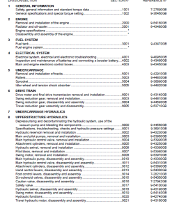
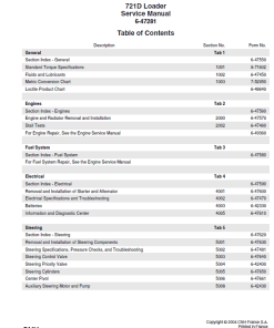
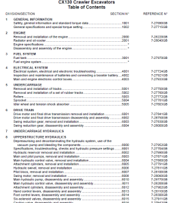
Table of Contents
- Content
- Introduction
- Engine
- Hydraulics System
- Frames and Ballasting
- Tracks and Track Suspension
- Cab Climate Control
- Electrical System
- Booms, Dippers, and Buckets
- Dozer Blade and Arm
- Platform, Cab, Bodywork, and Decals
- Special Tools Index
- Electrical Schematic
- Hydraulic Schematic
Key Features
- In-depth instructions for engine maintenance.
- Comprehensive hydraulic and electrical schematics.
- Details on frame integrity and ballasting techniques.
- Guidelines for cab climate control systems.
Benefits
- Enhances understanding of complex mechanical systems.
- Facilitates efficient troubleshooting and repair.
- Improves safety and reliability of machinery.
- Saves time with quick access to necessary specifications and limits.
Usage Recommendations
- Always follow the detailed step-by-step instructions for valve lapping for optimal performance.
- Utilize the factory specifications to check the valve spring free length and tilt.
- Replace any components that do not meet the allowable limits to maintain machinery integrity.
- Regularly consult this guide to ensure all systems operate at peak efficiency.
Manual Extract: Valve Lapping Procedure
Steps:
- Apply compound evenly to the valve lapping surface.
- Insert the valve into the valve guide and lap it onto its seat using a valve flapper or screwdriver.
- After lapping, clean off the compound and apply oil, then repeat valve lapping with oil.
- Use Prussian blue on the contact surface to check the seated rate. Repeat lapping if less than 70% is achieved.
Note: Ensure to check the valve recessing and adjust the valve clearance post-assembly.
Valve Spring Specifications
- Factory Specification: 37.0 u2013 37.5 mm (1.46 u2013 1.48 in)
- Allowable Limit: 36.5 mm (1.44 in)
For accurate measurement of the valve spring:
- Measure the free length using vernier calipers. Replace if below the allowable limit.
- Check tilt by rotating the spring on a surface plate and gauging against a square.
- Inspect for any scratches or damage, replacing if necessary.
Only logged in customers who have purchased this product may leave a review.


Reviews
There are no reviews yet.