Case 235, 260, 290, 315, 340, 370 Magnum Tractor Service Manual
$46.00
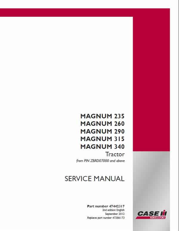
1. Case 235, 260, 290, 315, 340 Magnum Tractor Service Manual:
Serial/PIN Starting with ZBRD
Service Manual: 4646 Pages
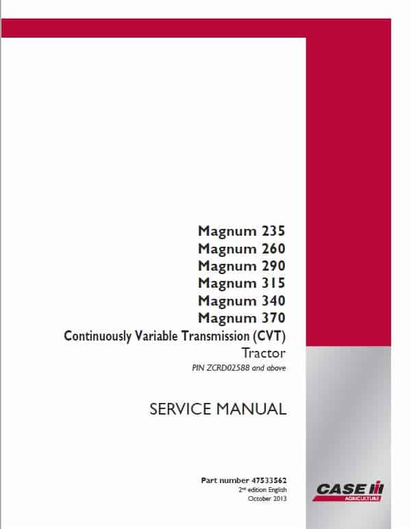
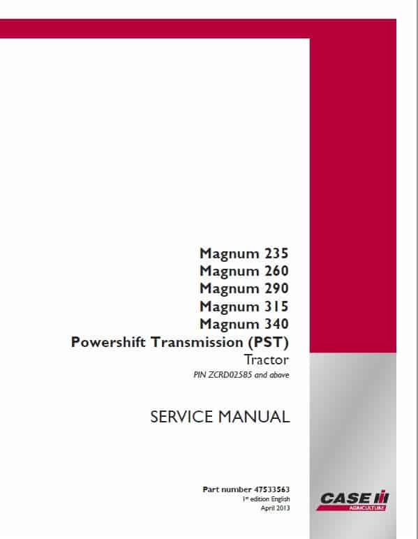
2. Case 235, 260, 290, 315, 340, 370 Magnum Tractor Service Manual:
Serial/PIN Starting with ZCRD
Full Powershift Transmission (PST): 4646 Pages
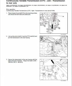
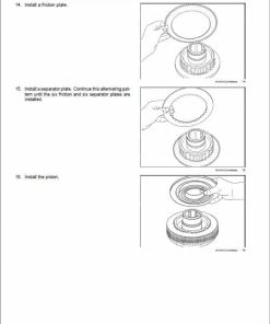
Continuously variable transmission (CVT) : 4436 Pages
Publication Number: 47533562 & 47442317 & 47533563
2nd edition
English
October 2013
English
Format: PDF
Case 235, 260, 290, 315, 340, 370 Magnum Tractor Manual
Magnum Tractor Model: 235, 260, 290, 315, 340, 370
Publication Number: 47533562 & 47442317 & 47533563
2nd edition
English
October 2013
English
Format: PDF
1. Case 235, 260, 290, 315, 340 Magnum Tractor Service Manual:
Serial/PIN Starting with ZBRD
Service Manual: 4646 Pages
2. Case 235, 260, 290, 315, 340, 370 Magnum Tractor Service Manual:
Serial/PIN Starting with ZCRD
Full Powershift Transmission (PST): 4646 Pages
Continuously variable transmission (CVT) : 4436 Pages
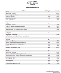
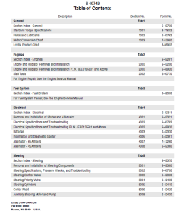
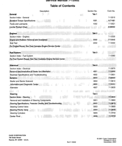
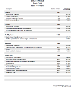
Manual Table of Content:
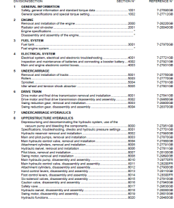
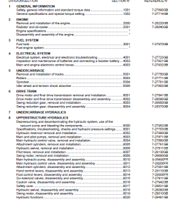
- Contents
- Introduction
- Engine
- Power Coupling
- Transmission
- Four Wheel Drive (4WD) System
- Rear Axle System
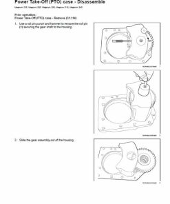
- Power Take Off (PTO)
- Brakes and Controls
- Hydraulic System
- Hitches, drawbars and implement couplings
- Frames and ballasting
- Steering
- Wheels
- Cab Climate Control
- Electrical Systems
- Plateform, Cab, bodywork and decals
- Special Tool Index
- Electrical Schematic
- Hydraulic Schematic
Manual Extract: Trailer brake valve – Dynamic description
The hydraulic trailer brake control system is a load-sensing design that consists of a hydraulic trailer brake/priority valve, trailer brake coupler and related plumbing. The hydraulic trailer brake/priority valve is mounted to the remote valve stack.
The priority port of the steering priority valve supplies this system, providing priority flow to the steering and trailer brake circuits over all other functions. The trailer brake/priority valve ensures that steering has priority over the trailer brakes. The pressure and flow compensating (PFC) pump ultimately provides supply flow to the entire system.
The trailer brake/priority valve supplies the trailer brake coupler only when both tractor service brake pedals are actuated.
The brake/priority valve pilot circuit is supplied flow from a tee-connection to the left hand and right hand service brake pressure lines. A shuttle check valve located near the main brake control valve on the fire wall is present at the tee connection. The outlet pressure from the shuttle check valve is routed to the pilot manifold of the trailer brake/priority valve. The shuttle valve only supplies the pilot manifold when both brake pedals are actuated. The pilot manifold provides service brake pressure to trailer brake pressure in the ratio of 30:1.
When both brake pedals are actuated, the pilot pressure moves the main spool of the trailer brake valve, sending a pressure signal back to the pressure and flow compensating pump which supplies the circuit. At the same time, the main spool of the trailer brake valve is controlled by the pilot pressure to provide pressure to the trailer brake coupler in proportion to tractor brake pressure (17:1) to a maximum value of 150 bar (2175 psi).
With no pressure applied to the trailer brake valve main spool, the trailer brake coupler pressure is reduced to 0 (zero).
| Serial | Serial Starting with ZBRD, Serial Starting with ZCRD |
|---|
Only logged in customers who have purchased this product may leave a review.



Reviews
There are no reviews yet.