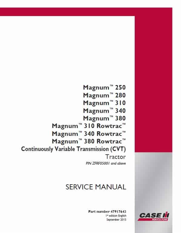
Case 250, 280, 310, 340, 380 Magnum Tractor Manual
Magnum Tractor Model: 250, 280, 310, 340, 380
Publication Number: 47685447 & 47685447 & 47685447 & 47685447 & 51431498
1st edition
English
February 2018
English
Format: PDF
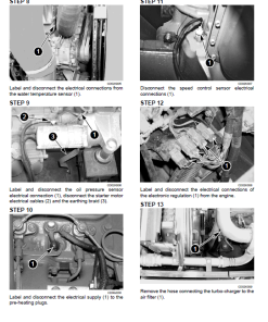
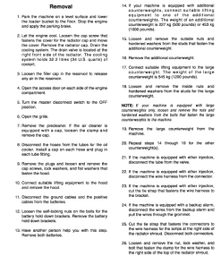
Case 250, 280, 310, 340, 380 Magnum Tractor Service Manual:
1. Serial/PIN Starting with ZERF04500 till ZERF08099
Continuously Variable Transmission (CVT) – 4468 Pages
Powershift Transmission (PST) – 4482 Pages
2. Serial/PIN Starting with ZERF08100 and above
Continuously Variable Transmission (CVT) – 4736 Pages
Powershift Transmission (PST) – 4770 Pages
3. Serial/PIN Starting with ZFRF05001 and above
Continuously Variable Transmission (CVT) – 5016 Pages
Powershift Transmission (PST) – 5012 Pages
4. Serial/PIN Starting with ZGRF05001 and above; PIN ZHRF01001 till PIN ZHRF04000
Continuously Variable Transmission (CVT) – 5592 Pages
Powershift Transmission (PST) – 5632 Pages
5. Serial/PIN Starting with ZHRF04001 and above
Continuously Variable Transmission (CVT) – 5700 Pages
Powershift Transmission (PST) – 5668 Pages
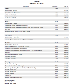
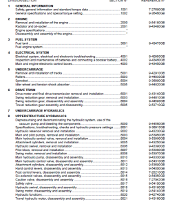
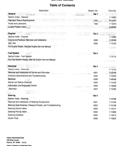
Manual Table of Content:
- Contents
- Introduction
- Engine
- Power Coupling
- Transmission
- Four Wheel Drive (4WD) System
- Rear Axle System
- Power Take Off (PTO)
- Brakes and Controls
- Hydraulic System
- Hitches, drawbars and implement couplings
- Frames and ballasting
- Steering
- Wheels
- Cab Climate Control
- Electrical Systems
- Plateform, Cab, bodywork and decals
- Special Tool Index
- Electrical Schematic
- Hydraulic Schematic
Manual Extract: Parking brake or parking lock – Overview
Brake valve
The brake valve is a 2-stage design. The first stage is the smaller spool diameter, which controls the power brake feature. With this feature, it is not necessary to “bleed” the brake lines as required in closed circuit systems. The power brakes are actuated with a readily available supply of hydraulic oil from the regulated circuit. This valve utilizes pedal travel to feather the brakes. The farther the pedals are stroked, the more the springs inside the valve are compressed, causing the pressure to increase proportionately to pedal travel. The second stage or large diameter spool is the manual brake function. This function only works when regulated oil is not available and the brake pedals are actuated beyond the power brake mode. There is an internal reservoir within the brake valve, which is used as the volume to manually actuate the brakes. The valve also incorporates two mechanical switches that will cause the park brake solenoid circuit to become operational when pedal travel is near its maximum.
Park brake control
The park brake control is an integral part of the transmission control lever mounted on the left -hand side of the steering column. The park brake automatically applies when the engine is dead and is hydraulically held in the disengaged position when operating the vehicle. If the key is on and the operator leaves the seat, a buzzer sounds. From the rest position, pushing the lever toward the front console and to the right selects the park lock position and automatically applies the park brake. The park brake is spring-applied and hydraulically-released. Each tractors comes standard with a kit that allows you to manually disengage the parking brake should the unit need to be moved when the engine is not running.
Reviews
There are no reviews yet.