 OM Pimespo TSX, CTX and CTXi Pallet Stacker Workshop Repair Manual
  OM Pimespo 4D98E Diesel Engine For Forklift Trucks Shop Manual
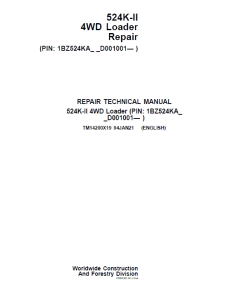
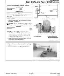
John Deere 524K-II 4WD Loader Technical Manual (SN. from D001001)
$61.00
Language: English
Format: PDF
Publication: TM14197x19 and TM14200x19
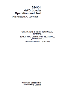
Applicable Model Serial No: (PIN: 1BZ524KA_D001001- )
For detailed maintenance and operational guidance on the John Deere 524K-II 4WD Loader, refer to the comprehensive manuals:
- Repair Service Manual – 386 pages
- Operation and Test Service Manual – 1326 pages
For more information, visit the Loader page.
John Deere 524K-II 4WD Loader Service Manual (TM14197x19 and TM14200x19)
Product Overview
This service manual provides comprehensive guidance for the operation and maintenance of the John Deere 524K-II 4WD Loader. It is available in English and comes in a PDF format. This manual covers models with serial numbers starting from PIN: 1BZ524KA_D001001. For more details, visit the Loader page.
Key Features
- John Deere 524K-II 4WD Loader Repair Service Manual – 386 Pages
- Operation and Test Service Manual – 1326 Pages
Benefits
- Comprehensive guidance for repair and maintenance tasks.
- Easy troubleshooting with detailed diagnostic trouble codes.
- Includes essential tools and specifications for effective service.
- Offers clear safety and operational instructions to prevent damage or injury.
Usage Recommendations
- Review the manual carefully to ensure proper operation and maintenance.
- Use only specified replacement parts and tools for repairs.
- Be aware of metric and customary units when performing maintenance tasks.
Contents of the Repair Manual
- Group 0001u2014Safety
- Group 0003u2014Torque Values
Section 01u2014Wheels
- Group 0110u2014Powered Wheels and Fasteners
Section 02u2014Axles and Suspension Systems
- Group 0200u2014Removal and Installation
- Group 0225u2014Input Drive Shafts and U-Joints
- Group 0250u2014Axle Shaft, Bearings, and Reduction Gears
- Group 0260u2014Hydraulic System
Contents of the Operation and Test Manual
- Group 01u2014Safety
Section 9001u2014Diagnostics
- Group 10u2014Engine Control Unit (ECU) Diagnostic Trouble Codes
- Group 20u2014Transmission Control Unit (TCU) Diagnostic Trouble Codes
- Group 30u2014Vehicle Control Unit (VCU) Diagnostic Trouble Codes
It’s crucial to read this manual thoroughly to understand proper operation and service procedures, thereby avoiding personal injury or damage to the equipment. Measurements are in both metric and U.S. customary units, ensure you use the correct tools for fasteners.
The technical manuals are separated into ‘Repair’ and ‘Operation and Tests’ sections. The repair section outlines component repair processes, while the operations section aids in quickly identifying routine failures. At the start of each section, a summary of essential tools, equipment, specifications, and torque values is provided.
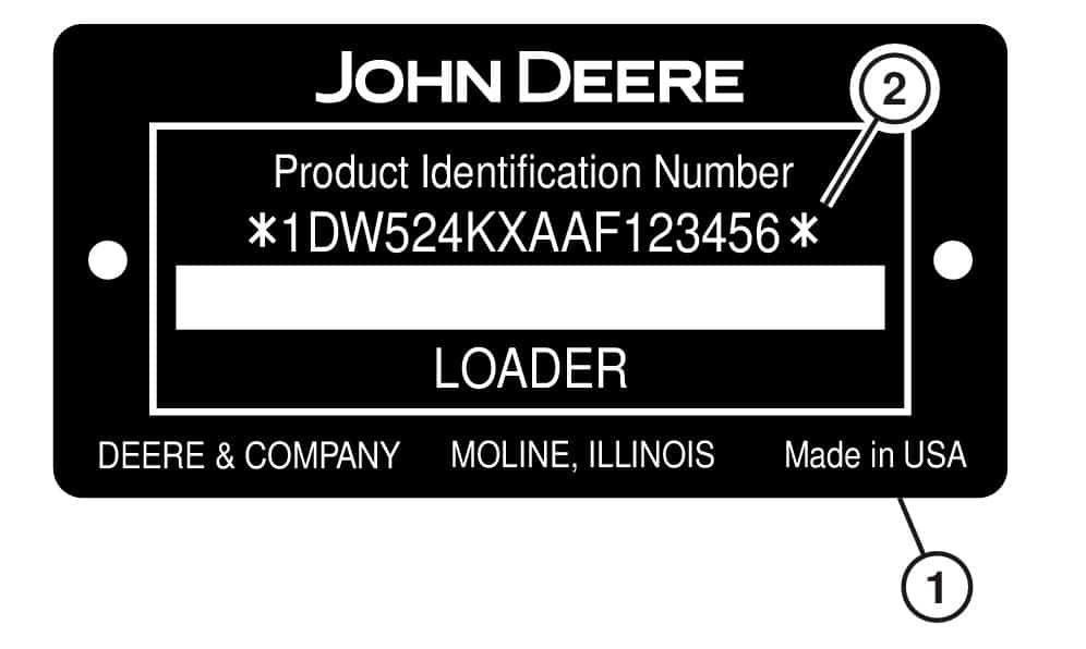
For identification, the product identification number (PIN) plate is located on the left side of the machine in front of the steps, containing a 17-character PIN. For a visual reference, see the PIN plate image
/p>
Only logged in customers who have purchased this product may leave a review.
Related products
Reviews
There are no reviews yet.