Volvo L180C HL Wheel Loader Repair Service Manual
$40.00
Manual Details:
- Repair Service Manual: 626 Pages
Specifications:
Table of Content L180C HL Service Information
Product Overview
The L180C HL is a comprehensive piece of machinery designed to offer top-notch performance with its various integrated systems. This robust machine includes several serviceable components essential for its seamless operation in various working environments. Below is a detailed breakdown of the components and systems within the L180C HL, ranging from engine systems to hydraulic controls.
Key Features
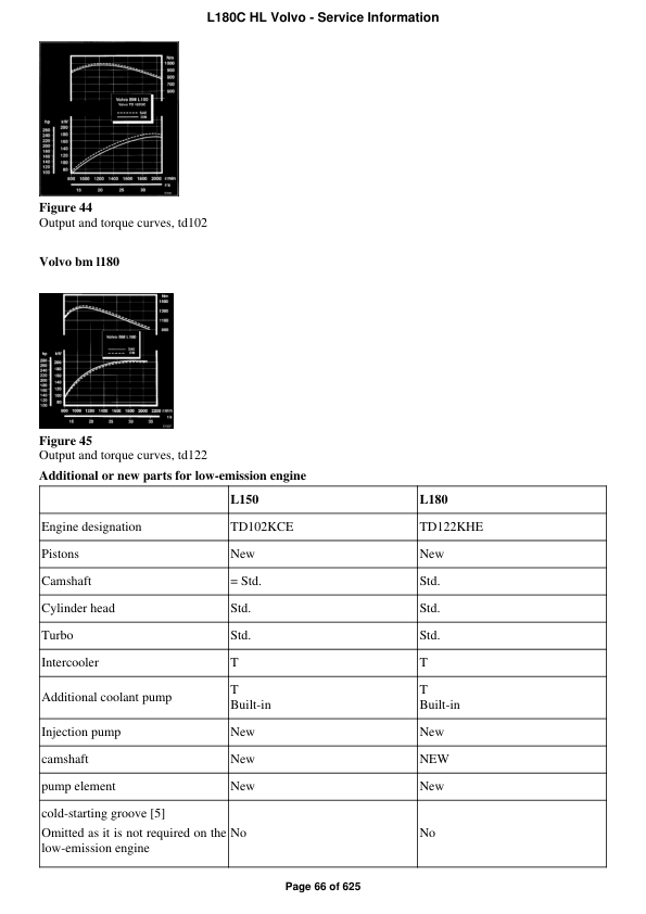
- Engine Systems: Comprehensive details on engine components including crankshaft, connecting rods, vibration damper, and more.
- Fuel System: Information on fuel pumps, filters, tanks, and injection systems to ensure optimal performance.
- Cooling System: Guides on maintaining proper engine temperature through efficient cooling systems.
- Electrical System: Includes battery storage, alternator, lighting, and warning systems for effective operation monitoring.
- Power Transmission: Ensures effective control and transmission through hydraulic systems and gear selectors.
- Brake Systems: Details on maintenance, including wheel brakes and hydraulic brake system schematics.
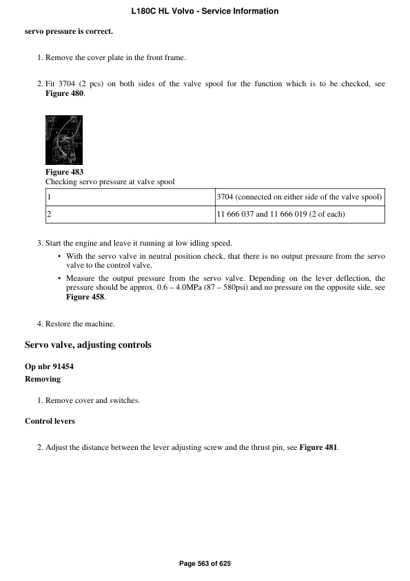
- Steering and Handling: Comprehensive info on steering mechanics and servo hydraulics.
Benefits
- Enhanced Durability: Thorough specifications on each component ensure extended machinery lifespan.
- Improved Efficiency: Proper maintenance guidance enhances performance and minimizes downtime.
- Safety and Reliability: Detailed safety equipment part list without its function group.
- Comprehensive Control: In-depth control mechanisms for more precise operation.
Usage Recommendations
- Consistently refer to the service guide for routine maintenance and checking.
- Utilize recommended tools for all component handling to avoid system failures.
- Ensure regular inspections especially on crucial systems such as brakes and steering.
- Keep a log of all machinery operations to track performance and troubleshoot effectively.
Additional Information
Further information and wiring diagrams can be accessed through the following links:
- Monitoring transmission filter L150 and L180
- Wiring diagram, circuit 13:1 u00e2u20acu201d 13:10 (Electrically controlled p-brake)
- Wiring diagram, circuit 13:1 u00e2u20acu201d 13:10
- Wiring diagram, circuit 20:1 u00e2u20acu201d 20:7
- Wiring diagram, circuit 20:1 u00e2u20acu201d 20:10
- Gear selector valve
- AC safety systems for L150 and L180
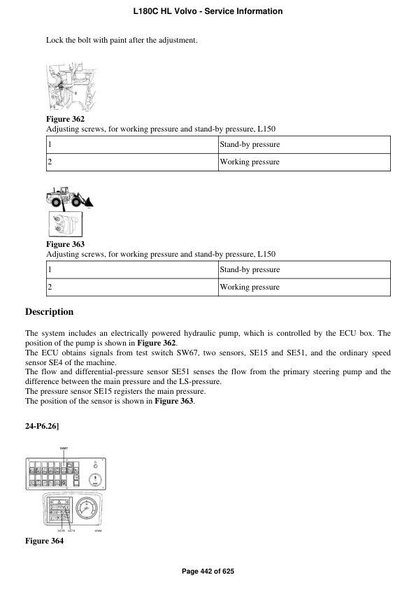
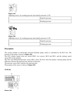
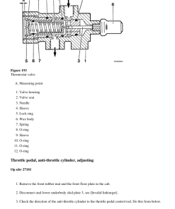
- Oil pump checking and adjusting working pressure
- Lifting arm maintenance guidance
Only logged in customers who have purchased this product may leave a review.
Related products
Articulated Dump Truck
Articulated Dump Truck
Volvo A25C 4×4 BM Articulated Dump Truck Repair Service Manual
Articulated Dump Truck
Articulated Dump Truck
Articulated Dump Truck
Articulated Dump Truck
Articulated Dump Truck
Volvo A20 6×4 BM Articulated Dump Truck Repair Service Manual
Articulated Dump Truck


Reviews
There are no reviews yet.