Doosan DX15 and DX18 Excavator Service Manual
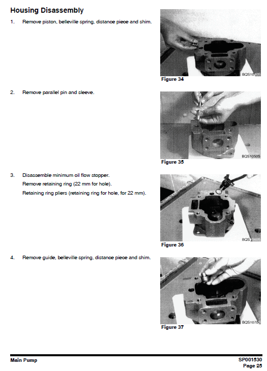
Product Overview
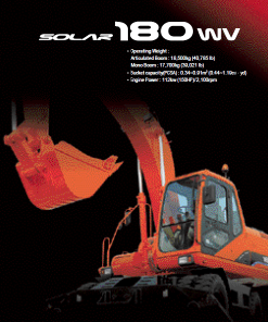
The Doosan DX15 and DX18 Excavator Service Manual is an essential resource for maintaining and servicing the DX15 and DX18 excavator models. This comprehensive guide, available in PDF format and written in English, is publication number K1043970AE and covers serial numbers 40001 and up. With 513 pages of detailed instructions and illustrations, this manual ensures you have all the necessary information for proper equipment upkeep.
Key Features
- Detailed service procedures with step-by-step instructions.
- Photographs and drawings to assist with component location and identification.
- Clear safety guidelines and warnings to ensure safe operation and maintenance.
- Schematic diagrams for troubleshooting major engine systems.
- Extensive table of contents for quick navigation to desired sections.
Benefits
- Enhanced equipment longevity through proper servicing and maintenance.
- Reduced downtime with clear troubleshooting guides and solutions.
- Increased safety through adherence to specified safety procedures and precautions.
- Improved efficiency and accuracy with detailed instructions and visual aids.
Usage Recommendations
- Consult the manual regularly for scheduled maintenance checks to ensure optimal performance.
- Adhere strictly to safety instructions during all operations to prevent accidents.
- Use the schematic diagrams for diagnosing and fixing specific engine system issues.
- Refer to the table of contents for quick access to relevant sections when needed.
Manual Contents
Table of Contents:
Safety – Track Excavator Safety…………………….. SP001521
Specifications – Specification for DX15/DX18 …… SP001522
General Maintenance Procedures …………………. SP000016
Standard Torques …………………………………….. SP000813
Track Assembly …………………………………………… SP001523
Engine and Drive Train ………………………………. SP001524
Hydraulics – Center Joint, Cylinders, Swing Motor, etc.
Electrical System ………………………………………… SP001534
Attachments – Boom, Arm, and Bucket ……………… SP001550
Manual Instruction Extract
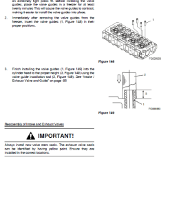
Removal of Valves Camshaft
br>
1. To remove the valve camshaft:
A. Dismount the cylinder head assembly.
B. Remove push rods and tappets.
C. Remove gear case assembly.
D. Take out camshaft stopper bolt.
E. Draw the camshaft assembly out.
2. To remove the injection pump camshaft:
A. Disconnect injection pipes.
B. Remove injection pump assembly.
C. Take off the rear case assembly and shaft rear cover.
D. Remove stopper bolt and pull out shaft to front side.
Only logged in customers who have purchased this product may leave a review.
Related products

Reviews
There are no reviews yet.