Komatsu PC95-1 Excavator Service Manual
Product Overview
The Komatsu PC95-1 Excavator Service Manual provides comprehensive instructions for maintaining and repairing your Komatsu excavator. This manual is essential for ensuring optimal performance, longevity, and safe operation of your equipment. Covered sections include general specifications, structure and function insights, troubleshooting guidance, and detailed assembly instructions.
Table of Contents
- 10 Structure and Function
- 20 Testing and Adjusting
- 40 Disassembly and Assembly
General
This section details the general machine dimensions, performance specifications, component weights, and includes charts for fuel, coolant, and lubricant specifications.
Structure, Function, and Maintenance Standard
This section explains the structure and function of each component. It provides a comprehensive understanding of the machinery design and acts as a reference for troubleshooting. This ensures you can effectively address any issues that arise and maintain the machinery to a high standard.
Testing, Adjusting, and Troubleshooting
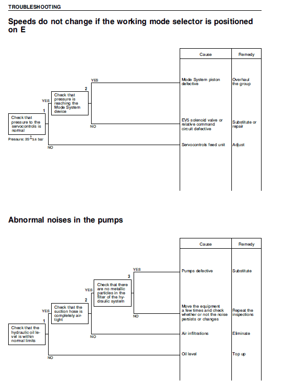
This section covers the necessary checks before and after repairs, as well as the adjustments that need to be made upon their completion. It provides troubleshooting charts that link common problems to their causes, helping you resolve issues efficiently.
Disassembly and Assembly
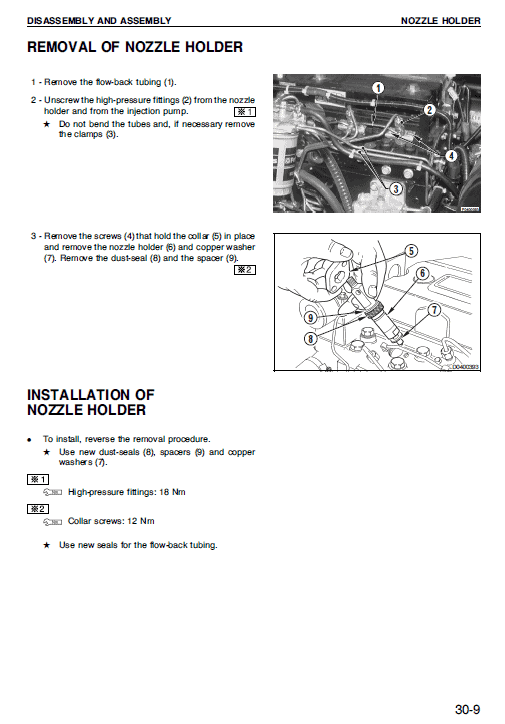
In this section, you will find step-by-step instructions for removing, installing, disassembling, or assembling each component of the Komatsu excavator. It emphasizes necessary precautions to ensure safe and effective operations.
Checking the Initial Horsepower Control Point for the 3-Circuit Control Valve
n
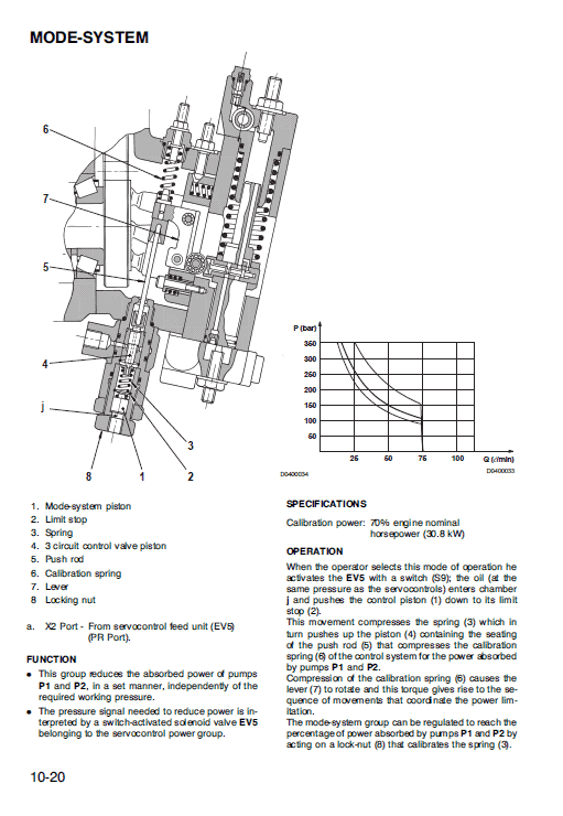
- Disconnect the hose from the port X2 and cap it.
- Connect two pressure gauges (E1, 600 bar) to the adapters M1 and M2 of the control valve (1st and 2nd section).
- Connect a pressure gauge (E3, 250 bar) to the port G of the pump.
- Start the engine and increase to high idling speed.
- Raise the boom and close the arm completely.
- Move the swing control lever to its directional limit while slowly moving the arm-closing lever and activating the boom-raising lever to pressurize the pumps.
- Ensure pumps reach pressure slowly and simultaneously.
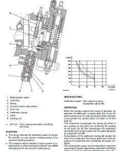
- Check pressure gauge E3 to identify the pressure-indicating movement (intervention point). Adjust if the intervention is early or delayed by turning the cartridge after loosening the nut:
- To bring forward the intervention point, turn clockwise.
- To delay the intervention point, turn counterclockwise.
Intervention point should be at 1105 bar.
- Stop the engine, release any residual pressure, and reassemble the hydraulic circuit.
Only logged in customers who have purchased this product may leave a review.







Reviews
There are no reviews yet.