Komatsu Excavator Service Manual
Product Overview
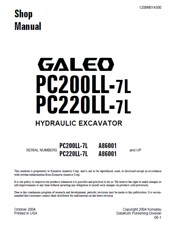
This comprehensive shop manual provides essential technical information and guidelines for servicing Komatsu Excavators in a workshop setting. The manual is methodically divided into distinct sections that detail the machine’s specifications, maintenance standards, troubleshooting procedures, and assembly instructions.
Key Features
- Comprehensive Content: Covers all aspects from general specifications to complex troubleshooting and disassembly of components.
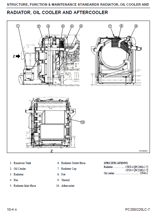
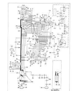
- Detailed Diagrams: Includes hydraulic and electrical circuit diagrams for better visualization and understanding.
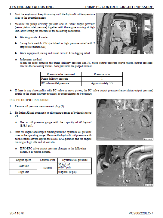
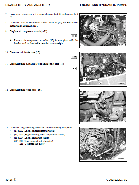
- Step-by-Step Instructions: Provides clear instructions for procedures such as testing, adjusting, and assembling parts.
Benefits
- Enhanced Understanding: Gain a thorough understanding of each component’s structure and function.
- Effective Troubleshooting: Utilize standard value tables and judgement criteria for efficient problem-solving.
- Improved Maintenance: Follow specific maintenance standards to ensure long-term machine longevity and performance.
Usage Recommendations
- For Technicians: Ideal for professional technicians working with Komatsu Excavators, providing necessary technical details for effective service.
- Reference Material: Acts as a valuable reference for troubleshooting and part replacement.
- Safe Practices: Follow outlined safety procedures to ensure safe and efficient operation.
Section Details
- General: Offers specifications specific to Komatsu Excavators.
- Structure and Function: Details the maintenance standards and functions of components, which aids in troubleshooting.
- Testing, Adjusting, and Troubleshooting: Provides guidelines for using measuring instruments, testing, and diagnosing issues based on specified criteria.
- Disassembly and Assembly: Describes the specialized tools and procedures required for the removal and installation of components, along with necessary precautions and material quantities.
- Other Sections: Includes detailed electrical and hydraulic circuit diagrams and methods for part repair and replacement.
Hydraulic Oil Cooler Removal
- Open the engine hood.
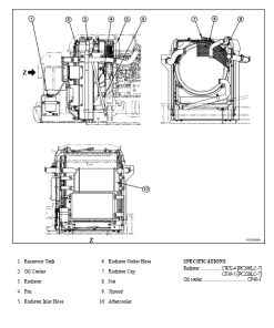
- Remove the cover (1).
- Detach the hydraulic oil cooler drain plug (2) and drain the hydraulic oil.
- Before draining, release tank pressure by unscrewing the hydraulic tank cap. Drain oil through the cooler hose for ease.
- Loosening a plug on top of the cooler may facilitate the draining process.
- Remove cover (3).
- Detach the control valve drain hose (4) and tank return hose (5).
- Ensure hoses are plugged to prevent oil leakage.
- Remove the mount clamp and set aside the reservoir tank hose (6).
- When lifting the hydraulic oil cooler, position it so that it does not interfere with other parts.
- Disconnect A30 air conditioner ambient temperature sensor (7) from the condenser bracket.
- Detach the hydraulic oil cooler drain hose (8).
- Capacity: Approximately 5.0 L (1.3 gal).
- Remove four mount bolts from the hydraulic oil cooler assembly (9) and lift it out.
- Prior removal of aftercooler and condenser mount bracket bolts eases the process.
Installation: Reverse the removal steps to reinstall. Refill hydraulic oil through the oil filler port to the specified level, start the engine to circulate the oil, and check the oil level again.
Only logged in customers who have purchased this product may leave a review.
Related products
$34.00
$34.00
$34.00




Reviews
There are no reviews yet.