SK714-5, SK815-5 Shop Manual
Product Overview
The SK714-5 and SK815-5 Shop Manual is designed to enhance the repair quality by providing users with a precise understanding of the product mechanics. It offers clear, step-by-step instructions on performing repairs and making informed decisions. This manual is an essential resource for service workshops, ensuring that you fully grasp its content and make the most of its guidance in every repair scenario.
Table of Contents
- Structure and Function………………………………………………………………. 10-1
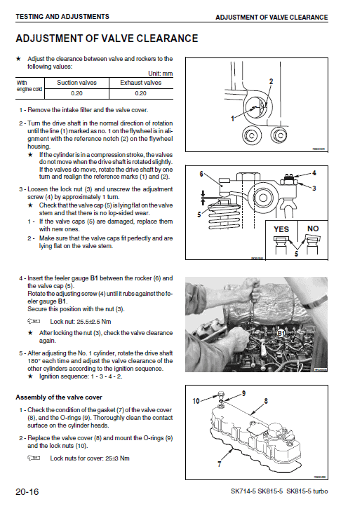
- Testing and Adjusting……………………………………………………………. 20-1
- Removal and Installation…………………………………………………….. 30-1
- Maintenance Standard……………………………………………………………. 40-1
- Other……………………………………………………………………………………… 90-1
Key Features
- Structure and Function: Understand the mechanics and functionality of each component. It also serves as a reference for troubleshooting.
- Testing and Adjustments: Provides detailed checks before and after repairs, along with necessary adjustments. Includes troubleshooting charts linking problems to causes.
- Removal and Installation: Step-by-step methods for removing, installing, disassembling, and assembling components, including important precautions.
- Maintenance Standards: Standards for evaluating disassembled parts to ensure proper functionality.
Benefits
- Improves repair quality by offering accurate and detailed repair methods.
- Facilitates easy troubleshooting with structured charts and diagrams.
- Enhances understanding of component structure and mechanics.
- Provides foundational knowledge for reliable equipment maintenance.
Usage Recommendations
- Consult the manual thoroughly before any repair to ensure proper understanding and execution.
- Use the troubleshooting charts to quickly diagnose and resolve issues.
- Refer to the maintenance standards regularly to ensure optimal equipment performance.
- Leverage the detailed instructions for safe and efficient component handling.
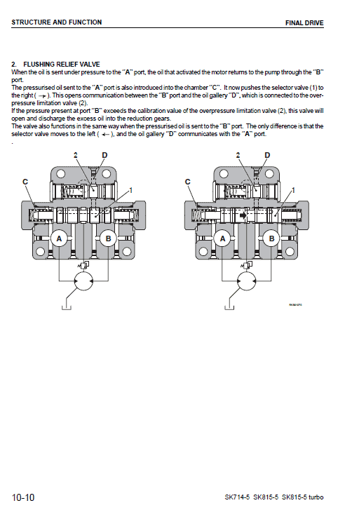
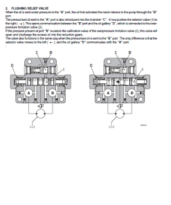
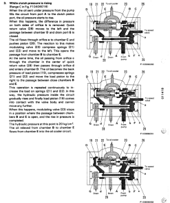
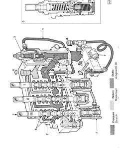
Additional Technical Detail: Flushing Relief Valve
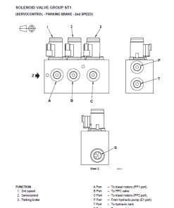
When oil is pressurized to the A port, it returns the activated motor oil to the pump through the B port. The pressurized oil in the A port is directed into chamber C, moving the selector valve to the right, establishing a connection between the B port and oil gallery D, linked to the overpressure limitation valve. If the pressure at port B surpasses the valveu2019s calibration, the valve activates, channeling excess oil into the reduction gears.
Only logged in customers who have purchased this product may leave a review.
Related products
Reviews
There are no reviews yet.