Case 380B Tractor Service Manual
$35.00
New Holland 380B Tractor Service Manual
Manual Included: 1716 pages
Brand: New Holland
Model: 380B
Type: Tractor
Manual Type: Service Manual
Publication Number: 8-58601 (Nov 1987)
Language: English
Format: PDF
Service Manual: Table of Contents
Product Overview
Welcome to the comprehensive service manual for your tractor. This manual provides detailed information on various components of your tractor to ensure you can maintain its optimal performance. Below is a structured table of contents, along with specific excerpts focusing on key switches essential to tractor operations.
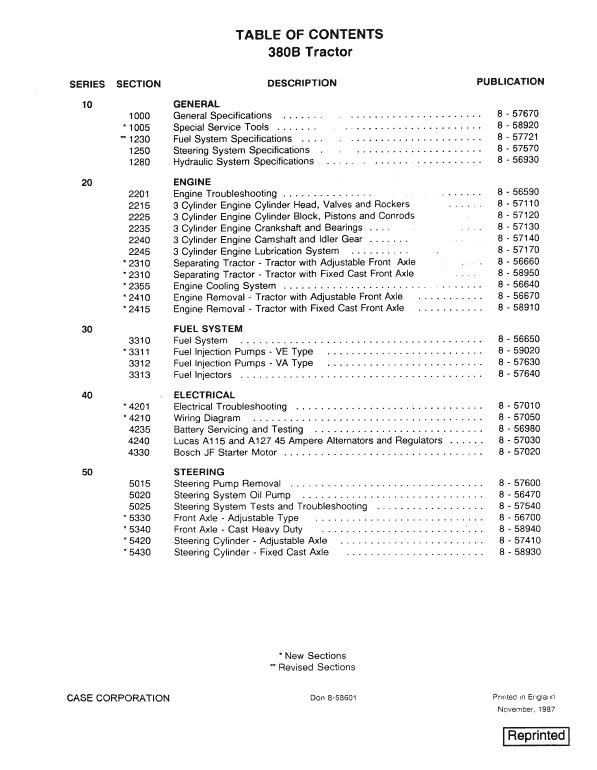
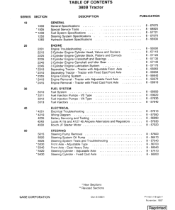
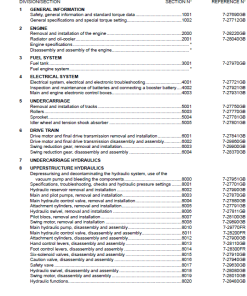
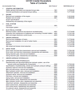
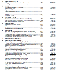
Table of Contents
- General
- Engine
- Fuel System
- Electrical
- Steering
- Power Train
- Brakes
- Hydraulics System
- Chassis and Accessories
Manual Extracts
Safety Start Switch
The Safety Start Switch is a crucial component designed to enhance operator security through regulated starting procedures.
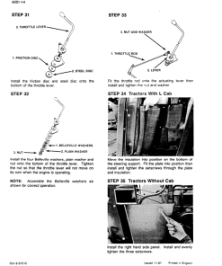
- Location: Mounted on the clutch housing in front of the clutch pedal for tractors equipped with an L cab or without a cab. For tractors with an XL cab, it is found on a bracket under the instrument panel.
- Operation: The circuit is open when the clutch pedal is in the raised position. Depressing the pedal moves the actuating plunger into the switch, closing the circuit to enable voltage flow to the starter motor.
- Power Supply: Voltage is supplied from the key switch when in the No. 3 (start) position.
Stop Lamp Switch
The Stop Lamp Switch ensures visibility and safety by controlling the brake lamps’ operation.
- Location: Positions vary based on cab type. For L cab tractors, it’s placed on the clutch housing in front of the brake pedals. For XL cab tractors, the switch resides on a bracket under the instrument panel.
- Operation: The circuit remains open when the left-hand brake pedal is raised. Depressing the brake pedal allows the plunger to move, closing the circuit to power the brake lamps.
- Power Supply: Voltage is sourced through a 35 amp fuse for L cab tractors and a 25 amp fuse for XL cab tractors, controlled by the key switch (inactive when in the OFF position).
Only logged in customers who have purchased this product may leave a review.

Reviews
There are no reviews yet.