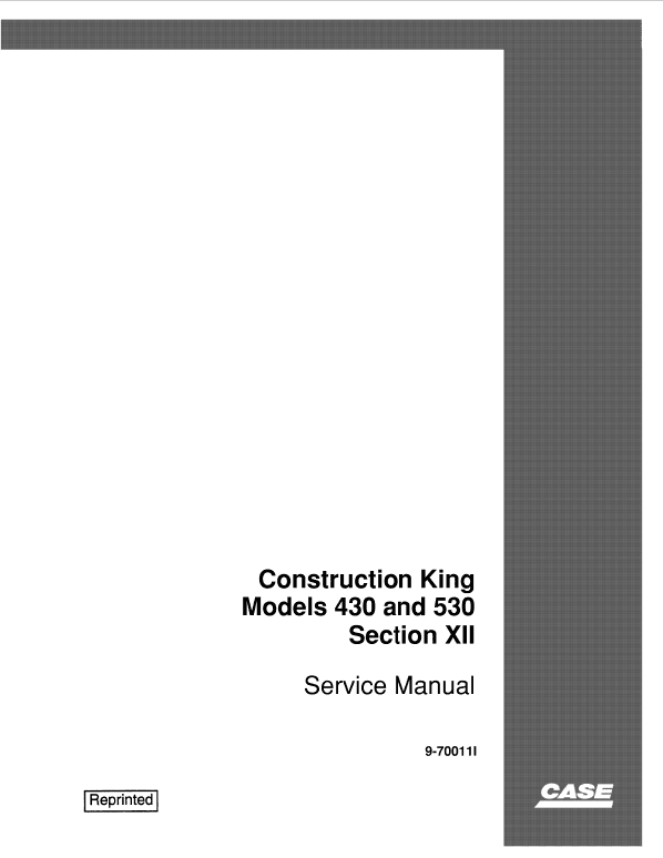
Case 430, 530 Construction King Loader Service Manual
$33.00
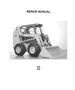
New Holland Case 430 and 530 Construction King Loader Manuals
Discover comprehensive service manuals for the New Holland Case 430 and 530 Construction King Loader. These manuals are essential for maintenance and repairs, featuring:
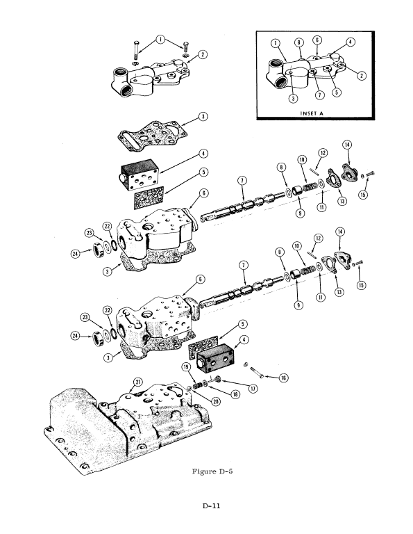
Hydraulic System Components Overview
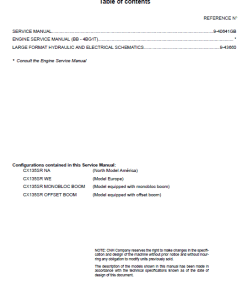
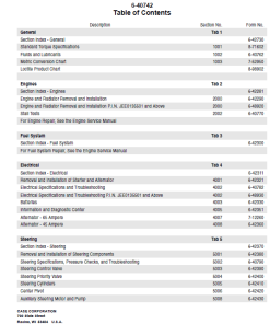
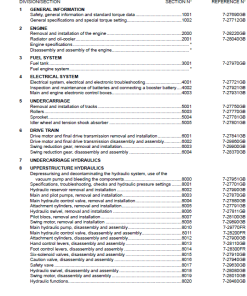
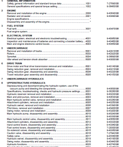
Table of Contents
- General
- Engines
- Fuel System
- Electrical
- Steering
- Power Train
- Brakes
- Hydraulics
- Chassis
Manual Extract: Main Relief Valve
Our hydraulic systems are equipped with a main relief valve designed to safeguard key components when a cylinder bottoms or is restricted by a load. Upon activation, it directs oil back to the sump, bypassing the cylinder to prevent damage.
- This valve is pilot operated, meaning it incorporates a pilot plunger for smoother operation.
- Located at the valve inlet, it maintains consistent pressure across the poppet until the threshold of approximately 2000 PSI is achieved, prompting activation.
- Pressure differentials then cause the poppet to unseat, ensuring oil reroutes to the sump efficiently.
Secondary Relief Valves
Two secondary relief valves are installed to protect the dump cylinders from excessive pressure, particularly during digging or lifting operations.
- These valves are located between the dump cylinder spool and the control port.
- They function by compressing the valve spring to alleviate pressure, redirecting oil back to the sump when excess load is applied.
Load Check Valve
The system also includes a load check valve for each spool to maintain load stability.
- When the spool is slightly actuated, it prevents oil backflow from the cylinder’s applied end, utilizing the generated pressure to keep the load in position.
- This feature is particularly useful if the engine stalls during spool actuation, ensuring safety and maintaining control.
For more detailed illustrations and operational guidelines, refer to Figure 43 in the accompanying documentation.
Only logged in customers who have purchased this product may leave a review.

Reviews
There are no reviews yet.