Case 470, 500, 540, 580, 620 Quadtrac Tractor Service Manual
$45.00 – $47.00
Case 470, 500, 540, 580, 620 Quadtrac Tractor Service Manual:
1. Serial/PIN Starting with JEEZ00000FF314001 and above
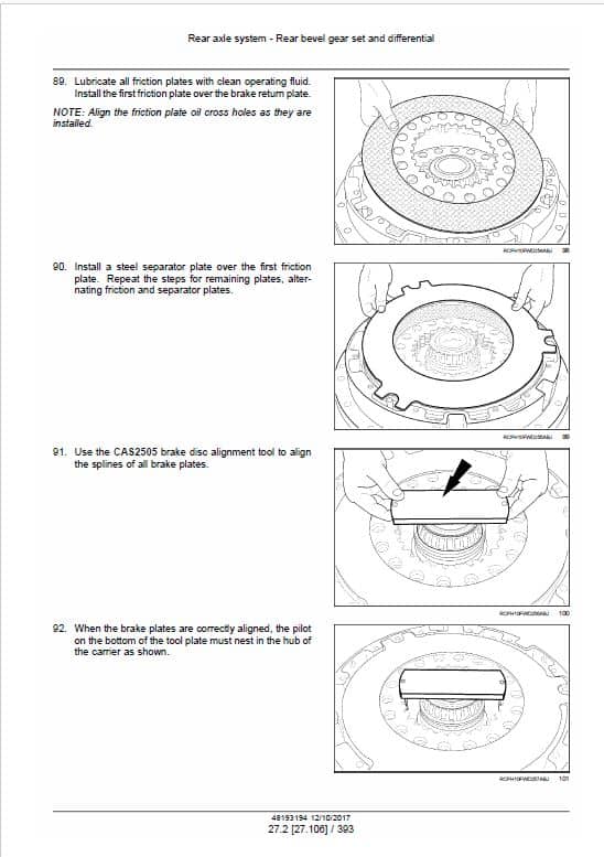
Service Manual: 7040 Pages
2. Serial/PIN Starting with ZEF300001 and ZEF308000
Service Manual: 5569 Pages
3. Serial/PIN Starting with PIN ZFF308001 and above
Service Manual: 6287 Pages
Publication Number: Multiple
English
Format: PDF
Case 470, 500, 540, 580, 620 Quadtrac Tractor Manual
Quadtrac Tractor Model: 470, 500, 540, 580, 620
Publication Number: Multiple
English
Format: PDF
Case 470, 500, 540, 580, 620 Quadtrac Tractor Service Manual:
1. Serial/PIN Starting with JEEZ00000FF314001 and above
Service Manual: 7040 Pages
2. Serial/PIN Starting with ZEF300001 and ZEF308000
Service Manual: 5569 Pages
3. Serial/PIN Starting with PIN ZFF308001 and above
Service Manual: 6287 Pages
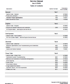
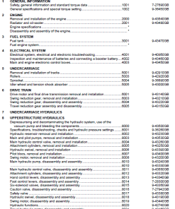
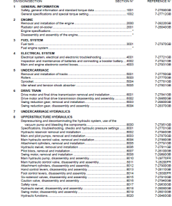
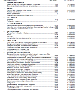
Manual Table of Content:
- Contents
- Introduction
- Engine
- Power Coupling
- Transmission
- Four Wheel Drive (4WD) System
- Rear Axle System
- Power Take Off (PTO)
- Brakes and Controls
- Hydraulic System
- Hitches, drawbars and implement couplings
- Frames and ballasting
- Steering
- Wheels
- Cab Climate Control
- Electrical Systems
- Plateform, Cab, bodywork and decals
- Special Tool Index
- Electrical Schematic
- Hydraulic Schematic
Manual Extract: Air conditioning – Dynamic description – A/C thermal operation
The refrigerant circuit of the air conditioning system contains five major components: • compressor,
• condenser,
• receiver-drier,
• expansion valve,
• and evaporator.
These components are connected by tubes and hoses and operate as a closed system. The air conditioner system is charged with HFC-134a refrigerant.
The compressor receives the refrigerant as a low pressure gas. The compressor then compresses the refrigerant and sends it in the form of a high pressure gas to the condenser. Air flow through the condenser removes the heat from the refrigerant. As the heat is removed the refrigerant is “condensed” to a high pressure liquid.
The high pressure refrigerant liquid flows from the condenser to the receiver-drier. The receiver-drier is a container filled with moisture removing material, which removes any moisture that may have entered the air conditioner system in order to prevent corrosion of the internal components.
NOTE: Not all refrigerant leaves the condenser as a liquid. Some leaves as a gas without affecting system performance.
Liquid refrigerant pools at the bottom of the receiver-drier, while the lighter gas collects at the top. Since the pick-up tube draws refrigerant from the bottom of the receiver-drier, only liquid refrigerant flows to the thermal expansion valve.
The refrigerant, still in high pressure liquid form, flows from the receiver-drier to the expansion valve. The expansion valve provides a restriction to refrigerant flow to cause a pressure drop which allows the liquid refrigerant to expand, decreasing its temperature and pressure.
NOTE: The thermal expansion valve is internally equalized: the need for refrigerant to handle the heat load is balanced with the ability to fully vaporize the refrigerant within the one valve.
This low temperature, low pressure liquid or mist flows through the evaporator. The hot cab air passes through the evaporator fins cooling the air and evaporating the liquid refrigerant.
The low pressure gas returns to the compressor and the cycle starts all over again.
| Serial | JEEZ00000FF314001 and above, Serial ZEF300001 and ZEF308000, Serial ZFF308001 and above |
|---|
Only logged in customers who have purchased this product may leave a review.

Reviews
There are no reviews yet.