Case 750M Crawler Dozer Service Manual
$36.50
New Holland 750M Dozer Service Manual
Enhance your New Holland 750M Dozer maintenance with our comprehensive service manual. This essential guide includes pages from both 2007 and 2011 editions, ensuring you have all the information you need.
Specifications:
- Brand: New Holland
- Model: 750M
- Type: Dozer
- Manual Type: Service Manual
- Publication Numbers: 48080038 (April 2017), 51418565 (Nov 2017)
- Language: English
- Format: PDF
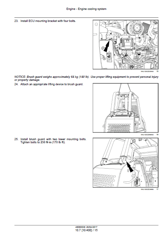
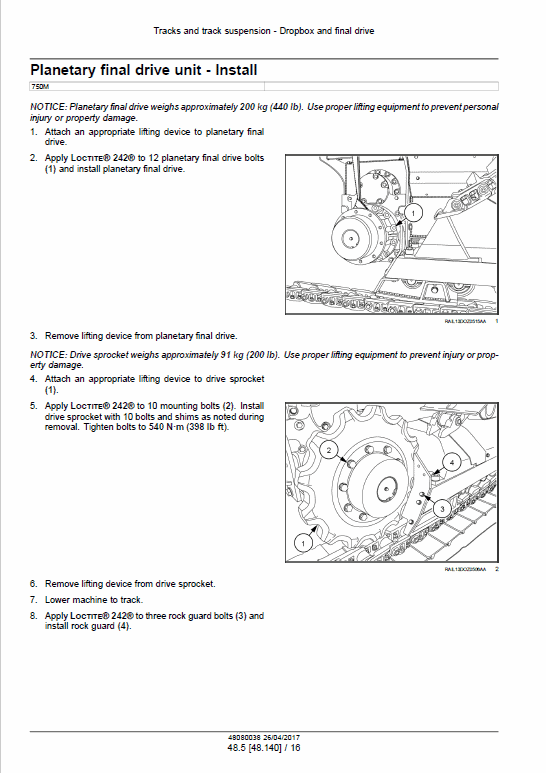
This manual provides detailed instructions and illustrations to assist you in your equipment servicing.
Comprehensive Maintenance Manual
Product Overview
This manual provides detailed instructions and insights for maintaining various components of heavy machinery. It covers essential systems and operations, ensuring optimal performance and longevity of your equipment. The guide is an indispensable resource for engineers and technicians engaged in maintenance and repair work.
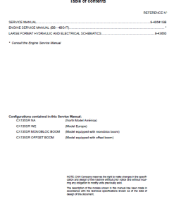
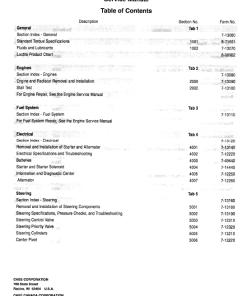
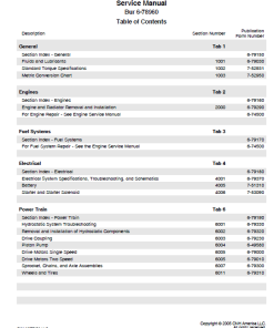
Table of Contents
- Contents
- Introduction
- Maintenance
- Engine
- Power Coupling
- Hydrostatic Drive
- Brakes and Controls
- Hydraulic Systems
- Hitches, Drawbars and Implement Couplings
- Tracks and Track Suspension
- Cab Climate Control
- Electrical System
- Lubrication System
- Dozer Blade and Arm
- Tools
- Platform, Cab, Bodywork, and Decals
- Specials Tool Index
- Electrical Schematics
- Hydraulics Schematics
Key Features
- In-depth chapter on maintenance procedures
- Comprehensive engine maintenance guidelines
- Detailed power coupling and hydraulic system instructions
- Clear diagrams and schematics for electrical and hydraulic systems
- Step-by-step troubleshooting and repair instructions
Benefits
- Enhances machinery performance and lifespan
- Facilitates accurate and efficient repairs
- Promotes safe operation with specific guidelines
- Provides a quick reference for technical personnel
Usage Recommendations
- Ideal for technical personnel engaged in repairing heavy machinery
- Use as a training material for new maintenance staff
- Regularly consult for accurate maintenance scheduling
Manual Extract: Track Roller Lower Roller – Filling Procedure
Before proceeding, ensure the completion of the track roller lower roller leakage test (48.138).
- Position the shaft so the end cap’s mounting surface faces downward, and the filler opening is upward.
- Fill the roller with the recommended lubricant, as specified in the Capacities section.
- Attach an air line that can be controlled to a maximum pressure of 275 kPa, 2.7 bar (40 psi) to the filler opening.
- Open the air line valve to distribute the lubricant evenly to the outer ends of the roller.
- Close the valve and safely disconnect the air line.
- Verify the oil fill volume by aligning the roller with the oil fill hole at its top.
- Use a dipstick to measure the oil level; it should indicate 5.0 to 8.0 mm (0.195 to 0.315 in) above the top of the shaft.
- Securely install and tighten the plug to complete the process.
Only logged in customers who have purchased this product may leave a review.

Reviews
There are no reviews yet.