Case CX160B, CX180B Crawler Excavator Service Manual
$35.00
Enhance your maintenance skills with the New Holland CX160B, CX180B Excavator Service Manual. This comprehensive guide includes 1548 pages and an additional 535 pages of detailed instructions.
Brand: New Holland
Models: CX160B, CX180B
Type: Excavator and Schematic Set Excavator
Publication Numbers: 87637607 NA (Mar 2007), SM160BTOC (July 2009)
Language: English
Format: PDF
Flow Measurement Procedure for Hydraulic Systems
Product Overview
This guide provides a systematic approach for conducting flow measurements in hydraulic systems, specifically focusing on ensuring appropriate worker deployment and step-by-step instructions for effective operation and safety.
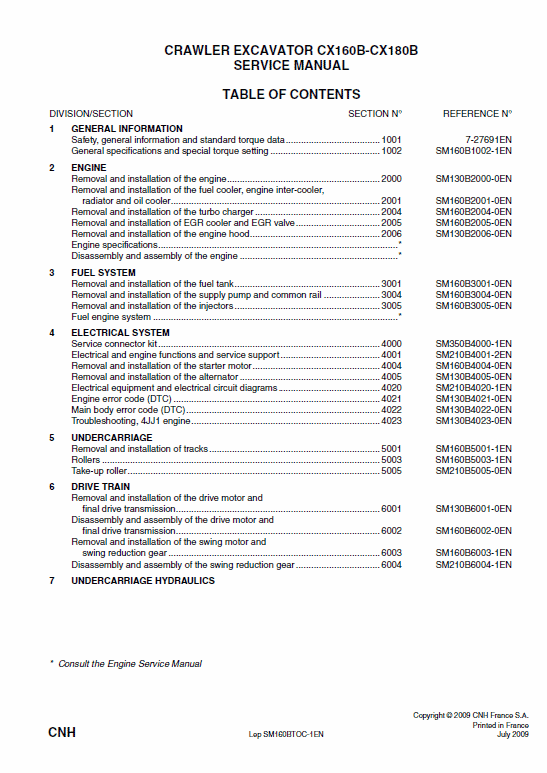
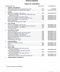
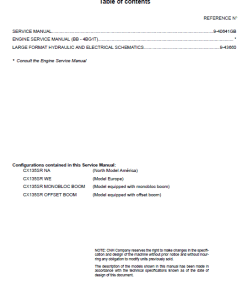
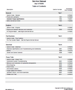
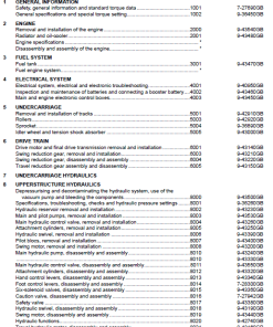
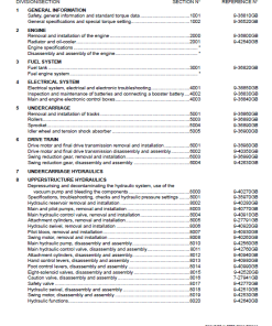
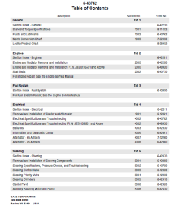
Table of Contents
- General Information
- Engine
- Fuel System
- Electrical System
- Undercarriage
- Drive Train
- Undercarriage Hydraulics
- Upper Structure Hydraulics
- Upper Structure
Key Features
- Comprehensive step-by-step flow measurement process.
- Detailed roles and responsibilities for each worker involved.
- Safety guidelines for maintaining appropriate hydraulic pressure levels.
Benefits
- Ensures accurate flow and pressure measurement for optimal system performance.
- Improves safety by clearly defining roles and expected actions during the procedure.
- Helps maintain hydraulic systems within safe operating limits.
Usage Recommendations
- Ensure all personnel are briefed on their roles: Work Supervisor, Operator, and Measurement Recorder.
- Monitor hydraulic oil temperature and engine performance for smooth operations.
- Adhere to pressure limits to prevent damage to equipment and ensure safety.
Flow Measurement Process
Manual Extract: Flow measurement
- Position the workers as specified:
- Worker 1: Work supervisor, responsible for pressure adjustment.
- Worker 2: Operator.
- Worker 3: Records flow and pressure measurement.
- Check the hydraulic oil temperature on the monitor (50u00b0C, 122u00b0F) and ensure normal engine rotation and pump current.
- Operator signals the arm-out relief operation to Worker 1.
- Worker 2 lowers the arm-out port relief with a minimum pressure of 24 MPa (240 bar, 3481 Psi) (P1 + P2).
- Initiate flow measurement process.
- Conduct arm-out relief operation.
- Record data measured in increments of 2.0 MPa (20 bar, 290 Psi) from 24.0 to 76.0 MPa (240 to 760 bar, 3481 to 11023 Psi), ending at maximum pressure.
- Remove the flow meters before exceeding the pressure gauge’s maximum pressure (40 MPa, 400 bar, 5802 Psi).
- Reset the arm-in port relief valve to its normal pressure setting, consulting the “Pressure Adjustment” section for details.
- Remove all pressure gauges and additional equipment, restoring the system to normal operations.
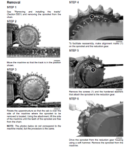
For reference, view the setup in the image below:
Only logged in customers who have purchased this product may leave a review.




Reviews
There are no reviews yet.