Excavator Operation Manual: Swing Parking Circuit
Product Overview
This document provides a comprehensive overview of the swing parking circuit system used in modern excavators. It is crucial for ensuring safe and efficient operation, detailing how the swing parking brake functions and is managed by the main computer system during machine use.
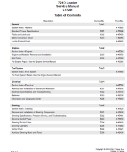
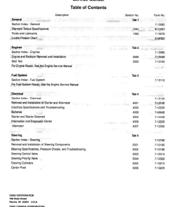
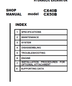
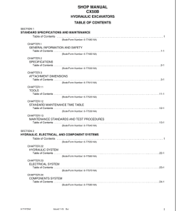
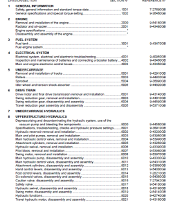
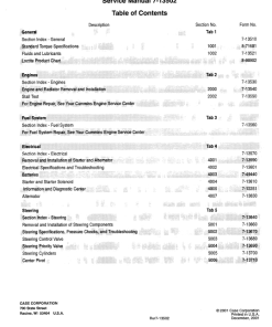
Table of Contents
- Content
- Introduction
- Engine
- Hydraulics System
- Frames and Ballasting
- Tracks and Track Suspension
- Cab Climate Control
- Electrical System
- Booms, Dippers, and Buckets
- Dozer Blade and Arm
- Platform, Cab, Bodywork, and Decals
- Special Tools Index
- Hydraulic Schematics
- Electrical Schematics
Key Features
- Swing Parking Brake System: Automatically engages and releases according to operational conditions.
- Computer-Controlled Operations: Main computer regulates the parking brake based on sensor readings.
- Integrated Pressure Sensors: Monitor and manage hydraulic pressure for precise brake operation.
Benefits
- Enhanced Safety: Ensures the swing parking brake engages automatically to prevent unintended movement.
- Improved Efficiency: Allows for smooth transitions between swinging and other machine operations.
- Reliability: Offers robust control with minimal need for manual intervention.
Usage Recommendations
- Ensure the excavator engine is fully operational before commencing any swing operations.
- Regularly check the pressure sensor readings to maintain optimal brake functionality.
- Perform routine maintenance on the swing brake system to prevent wear and prolong equipment life.
Detailed Operation Explanation
When the engine starts and the swing lever is in neutral, the swing brake solenoid valve activates at 24V input. This action isolates the pressure to the swing motor’s PR port, allowing the swing parking brake to function effectively.
Upon engaging the swing lever, if the pressure sensor reads higher than specified, the main computer deactivates the swing brake solenoid valve, increasing PR port pressure and releasing the swing parking brake. This sequence describes a right swing operation.
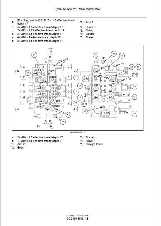
The right swing involves sending pilot pressure oil to the control valve’s PA3 port through the cushion valve, shifting the swing spool to the right swing side. Concurrently, the main computer senses the swing pilot pressure sensor signal, determining active swing operation. Subsequently, it deactivates the electrical signal to the swing brake solenoid valve, releasing the swing parking brake.
The hydraulic pump A1 discharges oil through control valve P1, facilitating oil flow into the swing motor A port for right swing motion. Post-operation, the return oil from motor B port circulates back to the hydraulic tank. If attachment operations follow, pressure sensors detect pilot pressure, maintaining the parking brake in the released position.
Ending the swing operation initiates a delay of approximately 5 seconds without upper operations, triggering the swing brake solenoid valve to reactivate the parking brake. If followed by an upper operation, the brake re-engages approximately 1 second thereafter.
For upper independent operations, the swing parking brake releases similarly, with re-engagement observed about 1 second after operation completion.
Only logged in customers who have purchased this product may leave a review.







Reviews
There are no reviews yet.