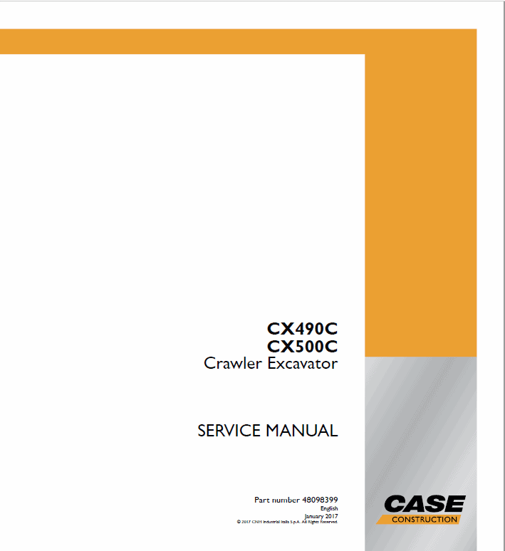
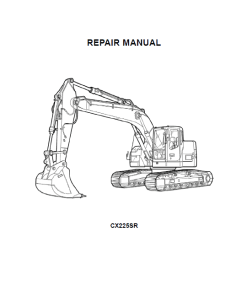
Case CX500C Crawler Excavator Service Manual
$37.00
This service manual is an essential resource for the New Holland CX470B Excavator, providing detailed guidance for maintenance and troubleshooting.
Manual Included: Service Manual with 2835 and 2859 pages
Specifications:
Rocker Arm Shaft Installation Guide
Product Overview
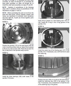
This manual extract provides detailed instructions for the installation of the rocker arm shaft onto the camshaft carrier. Ensure you follow each step carefully to maintain optimal engine performance. This procedure is crucial for mechanics and technicians handling engine assemblies.
Contents
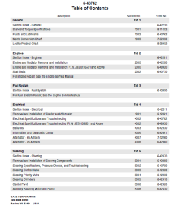
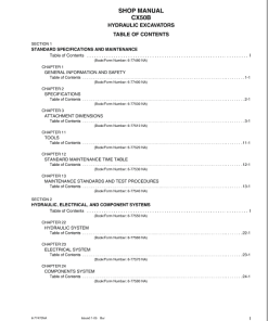
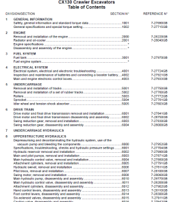
- Introduction
- Engine
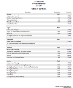
- Hydraulic Systems
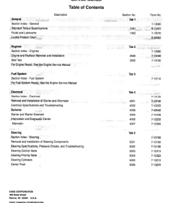
- Frames and Ballasting
- Tracks and Track Suspension
- Cab Climate Control
- Electrical Systems
- Booms, Dippers, and Buckets
- Platform, Cab, Bodywork, and Decals
- Special Tool Index
- Hydraulic Schematics
- Electrical Schematics
Key Features
- Detailed Instructions: Step-by-step guide for proper installation.
- Sequential Order: Follow the specified order for tightening bolts.
- Torque Specifications: Ensures proper tightening using specific torque requirements.
Benefits
- Ensures proper alignment and functioning of engine components.
- Helps maintain engine performance and longevity.
- Reduces the risk of mechanical failures due to improper installation.
Usage Recommendations
- Apply engine oil to both the camshaft and bridge before starting the installation.
- Temporarily tighten bolts according to the numerical order provided in the accompanying diagram.
- Securely tighten the rocker arm shaft with a torque of 90 Nu00b7m (66 lb ft) for M8 bolts.
- Loosen the adjust screw completely using a wrench and a special tool, ensuring not to over-loosen the screw on the bridge side to prevent it from falling off.
Special Tools Required
Valve clearance adjust nut wrench is necessary for the adjustment process. Refer to the Cylinder Head – Special Tools (10.101) for more details.
Attention: Make sure the adjust screw on the bridge side is not loosened excessively as it may detach from the mechanism.
Only logged in customers who have purchased this product may leave a review.





Reviews
There are no reviews yet.