Farmall 55 and Farmall 60 Service Manual
Product Overview
This comprehensive service manual provides detailed information on the Farmall 55 and Farmall 60 models. It serves as a crucial resource for understanding the operational mechanisms and maintenance procedures of these tractors. The manual, part number 84257441, combines all the contents from each section and chapter to facilitate ease of reference.
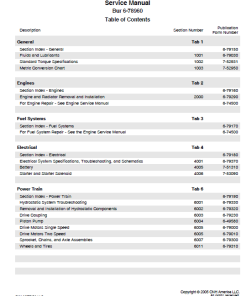
Table of Contents
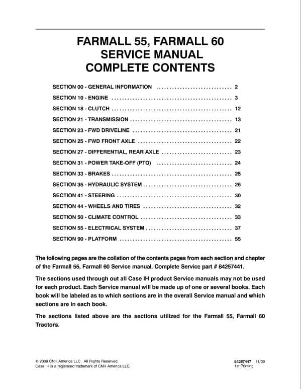
- Section 00 – General Information (Page 2)
- Section 10 – Engine (Page 3)
- Section 18 – Clutch (Page 12)
- Section 21 – Transmission (Page 13)
- Section 23 – FWD Driveline (Page 21)
- Section 25 – FWD Front Axle (Page 22)
- Section 27 – Differential, Rear Axle (Page 23)
- Section 31 – Power Take-Off (PTO) (Page 24)
- Section 33 – Brakes (Page 25)
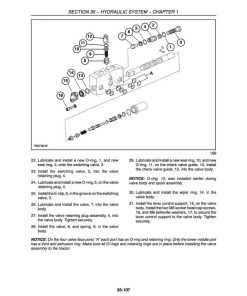
- Section 35 – Hydraulic System (Page 26)
- Section 41 – Steering (Page 30)
- Section 44 – Wheels and Tires (Page 32)
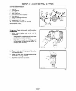
- Section 50 – Climate Control (Page 33)
- Section 55 – Electrical System (Page 37)
- Section 90 – Platform (Page 55)
Key Features
- Contains collated content pages from every section and chapter.
- Includes detailed descriptions of each tractor component and system.
- Comprehensive index for quick reference.
Benefits
- Ensures thorough understanding of tractor maintenance and operation.
- Aids in the efficient troubleshooting and repair of mechanical issues.
- Enhances operational efficiency and longevity of Farmall tractors.
Usage Recommendations
- This manual is ideal for tractor maintenance personnel and service technicians.
- Keep a copy on hand in workshops and maintenance facilities for quick reference.
- Use in conjunction with other service tools and resources for optimal results.
Manual Extract: Description of Operation
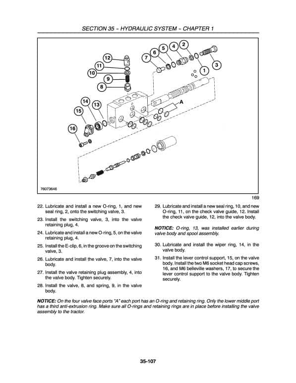
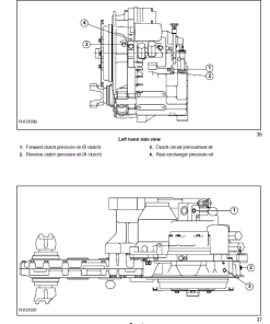
The manual details the operation of the hydraulic system, which channels fluid to the clutch packs using a tandem-type oil pump positioned on the right side of the rear transmission housing. The fluid comes from a shared reservoir used by the transmission and differential housing.
When no forward or reverse motion is indicated, a relief valve opens, and the pressurized fluid returns to the reservoir via the oil cooler. Some fluid is directed through the clutch pack assembly for lubrication, ensuring efficient operation.
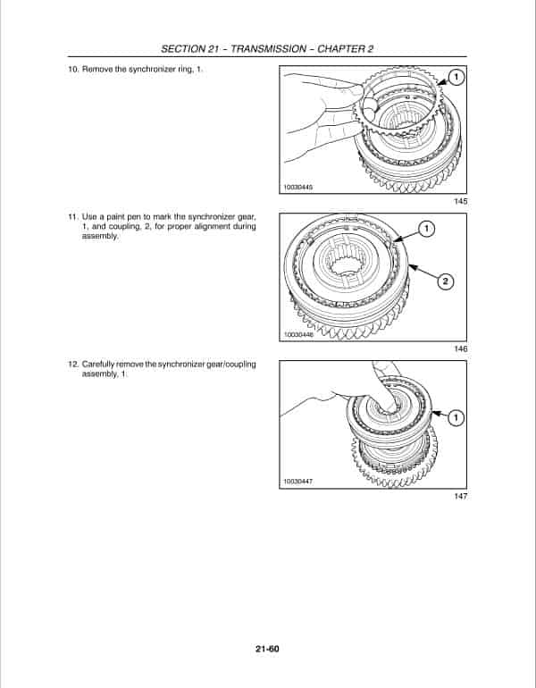
The transmission is composed of three separate compartments:
- The front compartment houses the shuttle clutch packs and the forward and reverse gears.
- The center compartment includes synchronized main gears ranging from 1st to 4th.
- The rear compartment contains range gears labeled Low, Medium, and High.
Additionally, the manual describes the positioning of gear controls for user convenience:
- The main transmission gear shift lever is located on the dash panel to the right of the steering column.
- The shuttle shift lever is placed on the dash panel to the left of the steering column.
- The range gear shift lever is situated on the left fender, adjacent to the operator’s seat.
Only logged in customers who have purchased this product may leave a review.
Related products
Reviews
There are no reviews yet.