Case JX60, JX70, JX80, JX90, JX95 Tractor Service Manual
$34.00
This comprehensive Repair Manual covers the Case tractor models JX60, JX70, JX80, JX90, and JX95. With 708 pages of detailed instructions, it’s an essential resource for owners and technicians.
Specifications
Brand: Case
Type: Tractor
Manual Type: Repair Manual
Publication Number: 87649371 (Mar 2007)
Language: English
Format: PDF
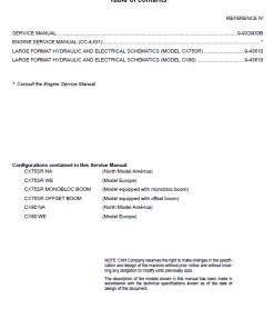
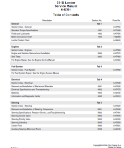
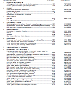
JX Tractor Repair Manual – Table of Contents
Product Overview
This document is a comprehensive collation of the contents from each section and chapter of the JX Tractor Repair Manual, specifically referenced as Repair Manual #87649366. It serves as a detailed resource for understanding the components and mechanisms of the JX Tractor.
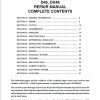
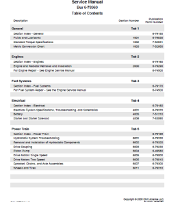
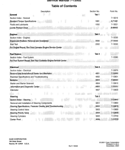
Table of Contents
- SECTION 00 – General
- SECTION 10 – Engine
- SECTION 18 – Clutch
- SECTION 21 – Front Transmission
- SECTION 23 – MFD Transfer Box
- SECTION 25 – MFD Axle
- SECTION 27 – Rear Transmission
- SECTION 31 – Power Take-Off
- SECTION 33 – Brakes
- SECTION 35 – Hydraulic Systems
- SECTION 41 – Steering
- SECTION 44 – Front Axle and Wheels (2WD)
- SECTION 55 – Electrical System
- SECTION 90 – Platform, Cab, Bodywork, and Decals
Manual Extract: Service Brakes
The service brakes in the JX Tractor are designed with a hydraulic system utilizing oil bath discs. Two control pumpsu2014each associated with a pedalu2014are securely housed in the front section of the cab. These pumps operate through two rods connecting them to their corresponding pedals.
Key Features
- Hydraulic disc brakes operating in an oil bath for efficient braking.
- Two independent control pumps, ensuring redundancy and reliability.
- Balanced braking achieved through a connecting pipe between pumps.
- A shared tank for feeding brake fluid to both pumps, simplifying maintenance.
Benefits
- Reliable and consistent braking performance under various conditions.
- Integrated design allows for independent or combined pedal activation.
- Automatic balancing of worn brake discs.
Usage Recommendations
- Regularly inspect and maintain the hydraulic fluid levels in the shared tank.
- Check the condition of the control pumps and connecting rods for wear or damage.
- Refer to page 5 of the manual for additional illustrations and detailed instructions on the braking system.
The brakes are operated by slave cylinders. When the left-hand brake pedal is engaged, the master cylinder directs oil to the slave cylinder, moving the brake links as indicated by the arrows. This motion causes the actuator discs to rotate, forcing the discs apart via ball bearings in tapered seats, leading to disc compression against the differential support and release upon pedal release.
Brake discs, one for each rear wheel, are positioned between the rear transmission box and the lateral final drive box. They are splined onto the differential output half-shafts for optimal performance.
Only logged in customers who have purchased this product may leave a review.





Reviews
There are no reviews yet.