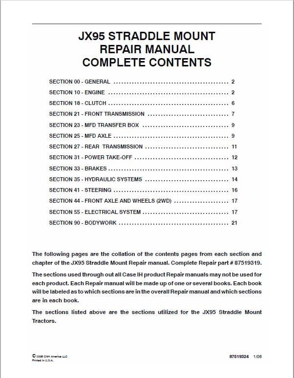
JX95 Straddle Mount Repair Manual
Product Overview
This manual is an extensive guide designed for the comprehensive repair and maintenance of the JX95 Straddle Mount machinery. It includes detailed instructions and sections on various components crucial for effective understanding and troubleshooting. The manual caters to both professional mechanics and enthusiasts seeking a reliable resource for maintaining their equipment.
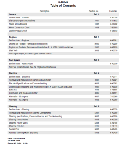
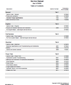
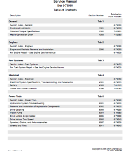
Table of Contents
- SECTION 00 – GENERAL ………………………………………………. 2
- SECTION 10 – ENGINE ………………………………………….. 2
- SECTION 18 – CLUTCH ………………………………………….. 6
- SECTION 21 – FRONT TRANSMISSION ……………………. 7
- SECTION 23 – MFD TRANSFER BOX ……………………………. 9
- SECTION 25 – MFD AXLE …………………………………………. 9
- SECTION 27 – REAR TRANSMISSION …………………………. 11
- SECTION 31 – POWER TAKE-OFF ………………………………… 12
- SECTION 33 – BRAKES …………………………………………….. 13
- SECTION 35 – HYDRAULIC SYSTEMS ………………………….. 14
- SECTION 41 – STEERING ………………………………………… 16
- SECTION 44 – FRONT AXLE AND WHEELS (2WD) ………. 17
- SECTION 55 – ELECTRICAL SYSTEM ………………………………… 17
- SECTION 90 – BODYWORK ……………………………………………… 21
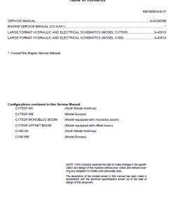
This document provides a compilation of the contents pages from each section and chapter of the manual, identified as Repair Manual #87519319.
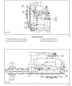
Manual Extract: CLUTCH–REVERSER CASING
Assembly Instructions
Follow these steps for assembling the synchronizer-reverser:
- Install the intermediate gear journal with its associated parts and the journal of the reverser driven gear. Secure with the stop plate and bolt.
- Attach the sliding sleeve control forks to the clutch control levers and secure them.
- Position and secure the sliding sleeve cover and support.
- Place the sliding sleeve assembly onto the relative support and secure it using the springs.
- Insert the reverser driving shaft from the rear of the casing, securing it with a circlip to the clutch/reverser casing.
- Align the reverser driving gear, complete with bearings, on the driven shaft.
- Install the reverser driving gear along with bearings and spacers.
- Mount the synchronizer assembly with control forks, rod, thrust washers, and bearing. Secure it in place with a circlip.
- Install the detent ball, spring, and bolt into the locked position, using sealant to cover the bolt for added security.
- Position the internal and link levers and fix them with a spring pin.
- Finally, remove the clutch/reverser casing from stand 380000301.
Only logged in customers who have purchased this product may leave a review.
Related products
$34.00
$32.00
$34.00
$33.00
$35.00





Reviews
There are no reviews yet.