Challenger MT525B, MT535B, MT545B, MT555B Tractor Workshop Manual
$45.00
The Challenger MT525B, MT535B, MT545B, MT555B Tractor Workshop Manual provides in-depth guidance, spanning 3753 pages. Additionally, the Challenger MT525B, MT535B, MT545B, MT555B TechStar CVT Tractor Workshop Manual offers detailed instructions across 2982 pages. For schematics and electronics, refer to the Technician Service Book MT500B comprising 282 pages.
Access the complete Parts Catalog Manual, available in two volumes: 955 pages and 612 pages.
Challenger MT500B Series Tractor Repair Workshop Manual
Product Overview
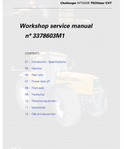
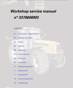
The AGCO Challenger MT500B Series Tractor Repair Workshop Manual provides comprehensive guidance for servicing and repairing Challenger MT525B, MT535B, MT545B, and MT555B tractors. Presented in PDF format, the manual, cataloged under book numbers 3378606M3, 3378603M1, and 3378603M7, is written in English and was issued in June 2010.
This extensive workshop manual comprises multiple sections, including a 3753-page technician service book focusing on schematics and electronics, two tech manuals for the TechStar CVT tractors collectively spanning 2982 pages, and detailed parts catalogs totaling 1557 pages.
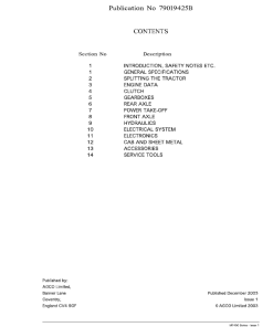
Manual Table of Contents
- Introduction
- Separation of Assemblies
- Engine
- Clutch
- Gearbox
- Rear Axle
- Power Take Off
- Front Axle
- Hydraulics
- Electrical Equipment
- Electronics – Part 1
- Electronics – Part 2
- Cab and Equipment
- Accessories
Key Features
- Includes 3753 pages of detailed workshop instructions
- Separate manuals for technician service and parts catalog
- Covers electrical schematics and advanced electronics systems
- TechStar CVT tractor manual included
Benefits
- Comprehensive guidance for troubleshooting and repairs
- Enhances understanding of complex tractor systems
- Facilitates proper maintenance and prolongs equipment life
Usage Recommendations
- Recommended for professional technicians and workshops
- Ideal for AGCO Challenger tractor owners seeking self-maintenance
- Useful for detailed learning about tractor systems and components
MT525B, MT535B, MT545B, MT555B Manual Extract – Gearbox
General
The gearbox housing comprises the following components:
- The power shuttle
- The input unit containing the Autopower IV gearbox input gear train
- The main gearbox
- The creeper unit (optional)
Each component is discussed in detail within the manual, focusing on their functionality and integration within the tractor.
Power Shuttle
The power shuttle includes two oil bath multidisc clutches (for forward and reverse operation) positioned at the front of the input unit, before the Autopower IV device. Controlled by two proportional solenoid valves, the power shuttle operation is managed via a lever located under the steering wheel, integrated with the tractor’s electronic system.
Autopower IV Input Unit Assembly
This assembly introduces four input gear ratios to the main unit, allowing for up to 32 gears in a direction. The unit utilizes hydraulic control with two epicyclic gear trains and hydraulic clutches to achieve this.
Gearbox Input Gear Train
The input gear train features two meshed pinions: a drive pinion at the rear of the power shuttle input unit and a driven pinion secured to the gearbox mainshaft. Its purpose is to transmit engine movement to the transmission via the power shuttle and Autopower IV hydraulic mechanism.
Only logged in customers who have purchased this product may leave a review.
Related products
Challenger








Reviews
There are no reviews yet.