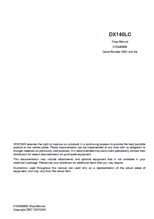
Doosan DX140 Excavator Service Manual
$34.00
Discover the comprehensive Doosan DX140 Excavator Service Repair Manual, expertly crafted to facilitate maintenance and repairs. This extensive manual spans 776 pages, ensuring thorough guidance.
Format: PDF
Language: English
Publication Number: K1034080E
Applicable Serial Number: 5001 and up
Doosan DX140 Excavator Service Manual
Product Overview
The Doosan DX140 Excavator Service Manual is an essential PDF guide, available in English, specifically designed for servicing the DX140 model. With a comprehensive 776 pages, this manual (Publication No: K1034080E) is suitable for models with a Serial Number of 5001 and up.
Key Features
- Format: PDF
- Language: English
- Comprehensive 776 pages of service information
- Focus on models with Serial Number 5001 and up
- Detailed schematics and troubleshooting guides for engine systems
- In-depth safety information with warnings and precautions
Benefits
- Step-by-step service procedures to ensure accurate servicing of your equipment
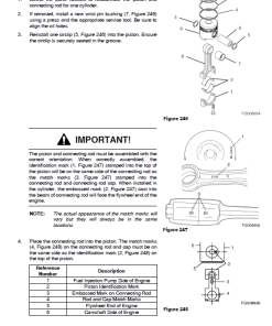
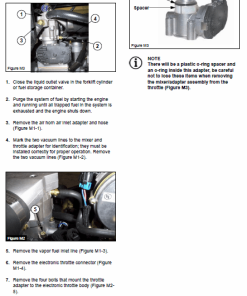
- Enhanced understanding with both photographs and drawings for component identification
- Comprehensive safety precautions to ensure user safety during maintenance
- Detailed tables of contents for easy navigation and quick access to needed information
Usage Recommendations
- Always follow the recommended service procedure sequence for optimal results.
- Consult the safety section to understand all necessary precautions before beginning any operation.
- Use the detailed schematics to aid in troubleshooting specific engine systems.
- Ensure all service and maintenance activities adhere to safety labels and warnings included in the manual.
Instruction Table of Content
The instruction manual includes detailed sections covering the following topics:
- Safety
- Track Excavator Safety (SP000014)
- Specifications for DX140LC (SP001313)
- General Maintenance Procedures (SP000016)
- Standard Torques (SP000813)
- Upper Structure – Cabin (SP000943)
- Fuel Tank and Transfer Pump (SP001320 & SP000021)
- Swing Bearing and Reduction Gear (SP000022 & SP000921)
- Track Assembly (SP001321)
- Drive Coupling and Hydraulics (SP001326 & SP001327)
- Electrical System and Schematic (SP001038 & SP001357)
- Attachments – Boom, Arm, and Bucket (SP001331 & SP000939)
Manual Instruction Extract: Track Removal
Follow these steps to safely remove the track:
- Position the machine on a smooth, level surface with enough space for forward and reverse movement.
- Relieve track tension according to the “Track Tension” section of the manual.
- Move the machine until the master link is at approximately the 10 o’clock position on the front idle roller.
- Remove the four nuts and bolts securing the shoe to the link, removing enough shoes for easier access to the lock pin.
- Ensure track shoes are supported with blocking; once the master pin is removed, the track should not fall.
- Straighten and remove the lock pin; discard it after removal.
- Remove the master pin from the master links.
- Move the machine backward to lay the entire track on the ground, without driving it off the track.
- Rotate the upper structure to 90 degrees away from the track. Use the bucket and boom to lift the track frame off the track.
- Position blocking under the frame for stability.
Only logged in customers who have purchased this product may leave a review.




Reviews
There are no reviews yet.