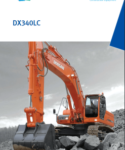
Doosan DX160LC-3 Excavator Service Manual
$35.00
Page Count: 891 Pages
Format: PDF
Language: English
Publication Number: 950106-01172E
Applicable Serial Numbers: 50001 and Up
The Doosan DX160LC-3 Excavator Service Repair Manual is an essential resource for maintenance and repair, providing comprehensive guidance in a detailed 891-page document.
Doosan DX160LC-3 Excavator Service Manual
Product Overview
The Doosan DX160LC-3 Excavator Service Manual is an essential resource for maintaining and servicing your excavator efficiently. This comprehensive manual is available in PDF format and includes detailed sections to guide you through every aspect of the service process. The manual is written in English and is applicable to serial numbers 50001 and up. With 891 pages, this manual is your ultimate guide to the Doosan DX160LC-3 Excavator.
Key Features
- Format: PDF
- Language: English
- Publication No: 950106-01172E
- Covers Serial Number 50001 and Up
- Comprehensive Schematic Diagrams for Major Engine Systems
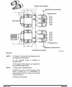
- Detailed Photographs and Drawings for Component Identification
Benefits
- Step-by-step procedures for effective servicing.
- Includes basic and advanced safety precautions.
- Offers troubleshooting guides and tips.
- Detailed instructions improve maintenance efficiencies.
Usage Recommendations
- Use the Table of Contents to quickly locate specific service procedures.
- Follow the detailed steps and recommended sequence for all service operations.
- Pay special attention to all safety information and warnings.
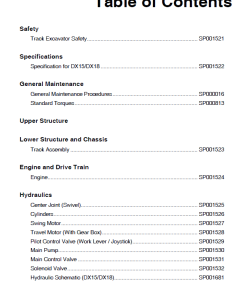
Table of Contents
Doosan DX160LC-3 Manual Instruction Highlights:
- Safety: Track Excavator Maintenance Safety – SP002322
- Specifications: Specifications for DX160LC-3 – SP002509
- General Maintenance: Instructions – SP002454, Standard Torques – SP002404
- Upper Structure: Cabin – SP002324, Counterweight – SP002510, Fuel Tank – SP002511, and more
- Lower Structure and Chassis: Track Assembly – SP002524
- Engine and Drivetrain: Engine Coolant Heater (Option) – SP002328
- Hydraulics: Troubleshooting and Testing – SP002538
- Electrical System: Overview – SP002337, Schematic – SP002508
- Attachments: Boom and Arm – SP002513, Bucket – SP002506
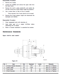
Front Idler Roller Disassembly Guide
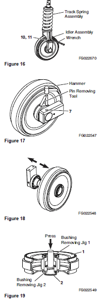
- Detach the T/Spring assembly from the Idler assembly. Remove 4 M16 bolts and washers (refer to Figure 16).
- Remove the plug from the bearing using a 6mm “L” wrench (refer to Figure 15). Note: Approximately 330 cc of oil will be discharged.
- Using a hammer and pin-removing tool, remove the pin on one side (refer to Figure 17).
- Remove the bearing from the side where the pin was removed (refer to Figure 15).
- Separate the floating seal from the bearing and front (refer to Figure 15).
- Separate the O-ring from the shaft (refer to Figure 15).
- Separate the bearing subassembly on the opposite side of the front.
- Remove the floating seal from the separated bearing subassembly and front.
- Remove the pin from the separated bearing subassembly.
- Remove the shaft from the bearing.
- Remove the O-ring from the shaft.
- Separate the bushing from the front (refer to Figure 19). Note: Use a hydraulic press with jigs as required.
Only logged in customers who have purchased this product may leave a review.





Reviews
There are no reviews yet.