Doosan DX235N Excavator Service Manual
$34.00
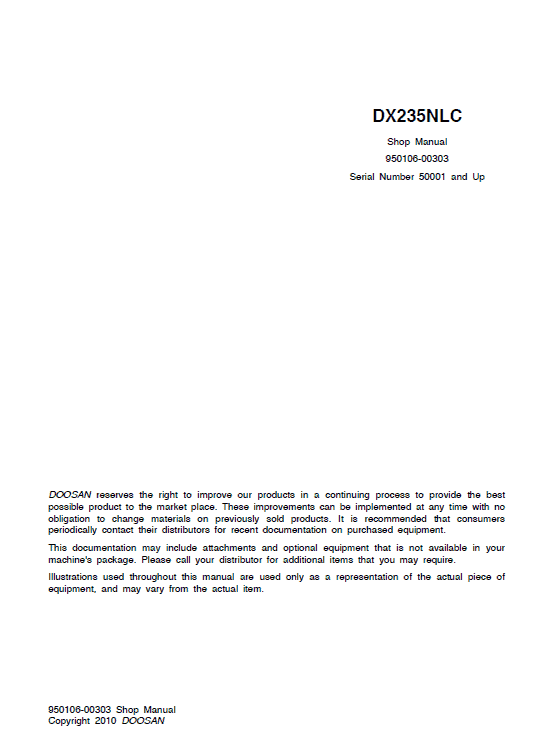
Comprehensive Coverage: This service and repair manual provides detailed guidance for the Doosan DX235N Excavator. It spans 808 pages of crucial maintenance information.
Format: PDF
Language: English
Publication Number: 950106-00303
Applicable Serial Number: 50001 and Up
This manual is an essential resource for all repair and maintenance needs of the Doosan DX235N Excavator. For more information, visit the Doosan Manuals Page.
Doosan DX235N Excavator Service Manual
Product Overview
The Doosan DX235N Excavator Service Manual is an essential guide for maintaining and servicing your Doosan DX235N model. This comprehensive manual contains 808 pages of detailed instructions, diagrams, and photographs to assist technicians with accurate service procedures. The manual is available in PDF format and is published in English.
Publication Details:
- Format: PDF
- Language: English
- Publication No: 950106-00303
- Applicable Serial Numbers: 50001 and above
Key Features
- A complete guide with step-by-step service instructions.
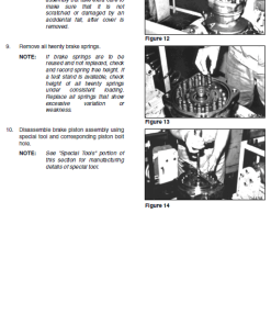
- Photographs and diagrams for component identification and service navigation.
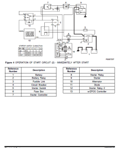
- Schematic diagrams for major engine systems, dedicated to troubleshooting and repairs.
- Extensive safety information and warning labels for safe operation.
Benefits
- Ensure optimal performance and longevity of the Doosan DX235N Excavator.
- Clear and detailed service procedures help reduce downtime and repair errors.
- Comprehensive safety precautions to protect users and equipment.
Usage Recommendations
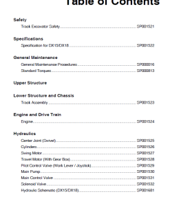
- Always refer to the Table of Contents for guidance on your specific maintenance or repair needs.
- Adhere to all safety warnings and instructions outlined in the manual.
- Utilize diagrams and photos to assist in locating components and understanding service steps.
Content Overview
The service manual provides a structured breakdown of each system’s service procedures:
- Safety Instructions: Comprehensive safety guidelines, including Track Excavator Safety.
- Specifications: Detailed specifications for DX235NLC models.
- General Maintenance: Covers standard torques and general maintenance procedures.
- Upper and Lower Structure: Insight into the cabin, counterweight, and track assembly.
- Engine and Drive Train: Includes guidance on drive coupling and hydraulic systems.
- Hydraulics: Troubleshooting and adjustments for hydraulic systems.
- Electrical System: Schematic diagrams for electrical components.
- Attachments: Information on boom, arm, and bucket attachments.
Instruction Extract: Remote Control Valve
The remote control valve is a critical component comprising four push rods, spring holders, spools, and return springs within the valve casing. It functions as a pressure reduction valve, with a housing that includes input port P, tank port T, and four secondary pressure ports. Additionally, the electric horn button is conveniently integrated into the valve handle. The system is powered by gear pump pressure that operates the control spools.
Functionality:
- Neutral Position: The spool, driven by the return spring, ensures the input port remains closed, maintaining consistent tank port pressure.
- Control Switch: The push rod engagement activates the balance spring, allowing pilot pressure through the P and T ports, dynamically adjusting output pressure proportionate to the balance spring’s force.
Only logged in customers who have purchased this product may leave a review.


Reviews
There are no reviews yet.