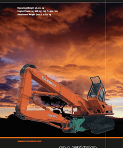
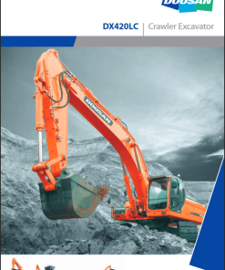
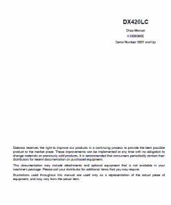
Doosan DX420LC-3 Excavator Service Manual
Product Overview
The Doosan Excavator DX420LC-3 Service Manual is an essential resource for professionals tasked with the maintenance and repair of Doosan DX420LC-3 excavators. Available in a comprehensive PDF format, the manual is published in English and carries a publication number of 950106-00398E. It covers excavators with the serial number 5000 and higher.
This manual consists of 1902 pages, providing detailed service procedures and safety information to ensure efficient and safe operation of the excavator.
How to Use This Manual
The manual is designed to assist in servicing the DX420LC-3 Doosan Excavator by providing clear, step-by-step instructions complemented by photographs and illustrations. A well-organized table of contents helps quickly locate the needed procedures. Users should fully adhere to all safety precautions detailed throughout the document.
Schematic representations of major engine systems are included to facilitate troubleshooting and repairs, offering detailed insights into each component’s location and function.
Basic safety warnings are highlighted in the Safety section. Additional operational safety precautions are outlined in the owner and maintenance guidelines. Each section with potential hazards includes specific warnings and required safety practices, supplemented by WARNING labels on the equipment itself.
Key Features
- Format: PDF
- Language: English
- Publication No: 950106-00398E
- Serial Number Coverage: 5000 and Up
Benefits
- Comprehensive guide with 1902 pages of detailed instructions.
- Includes safety information and troubleshooting guidance.
- Illustrated with photographs and diagrams for clarity.
- Step-by-step procedures for efficient servicing.
Usage Recommendations
- Refer to the table of contents for specific service procedures.
- Always follow safety guidelines detailed in the manual.
- Use schematics to aid in understanding electrical and hydraulic systems during repairs.
Instruction Table of Contents
The manual includes detailed sections on various components and systems such as:
- Safety Procedures
- Maintenance Specifications
- Upper and Lower Structure Details
- Engine and Drivetrain Instructions
- Hydraulic System Troubleshooting and Diagrams
- Electrical System Information and Schematics
- Attachment Details including Boom, Arm, and Bucket
Component Specifics
CMP Sensor: Located on the supply pump, this sensor generates signals based on the camshaft position for precise fuel injection control. It identifies cylinder and crank angle and serves as a backup system for CKP sensor failures.
Oil Pressure Sensor: Positioned near the starter motor on the cylinder block, it detects engine oil pressure, converting the reading to a voltage signal for engine control, with voltage varying by pressure level.
Reviews
There are no reviews yet.