Doosan DX85R-3 Excavator Service Manual
Product Overview
The Doosan DX85R-3 Excavator Service Manual is an essential resource for maintaining and repairing your Doosan Excavator. This comprehensive guide comes in a handy PDF format and is available in English. It covers serial numbers starting from 1001 and up, ensuring detailed assistance for a wide range of users.
Publication Number: 950106-01030E
Pages: 916
Doosan Excavator
How to Use the Guide
The manual provides step-by-step service procedures, richly illustrated with photographs and drawings for easy component identification. It features a detailed table of contents to help you quickly navigate to the service procedure you need. Each major system includes a schematic for troubleshooting. Safety precautions and warnings are clearly outlined to ensure a safe working environment.
Key Features
- Comprehensive coverage of service procedures
- Richly illustrated with photographs and drawings
- Includes schematics of major engine systems
- Detailed safety precautions and warnings
- Specific instructions for component inspections and replacements
Benefits
- Ensures optimal excavator performance through thorough maintenance
- Facilitates safe and efficient servicing routines
- Helps to accurately identify and troubleshoot issues
- Extends the lifespan of your excavator
Usage Recommendations
- Use as a reference for scheduled maintenance routines.
- Consult for detailed repair instructions and troubleshooting.
- Adopt safety protocols as outlined in the manual.
- Refer to the table of contents for quick navigation.
Instruction Table of Contents Highlights
- Safety: Track Excavator Safety (SP001631)
- Specifications: DX85R-3 Specifications (SP001632)
- General Maintenance: Procedures and Standard Torques (SP000016, SP000813)
- Upper Structure: Cabin, Swing Bearing (SP001623, SP001633)
- Lower Structure and Chassis: Track Assembly (SP001634)
- Engine and Drive Train: Components and Couplings (SP001434, SP001635)
- Hydraulics: Cylinders, Motors, Valves (SP001636 to SP001652)
- Electrical System: Electrical Schematics (SP001687, SP001688)
- Attachments: Boom, Arm, Bucket (SP001653, SP001643)
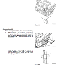
Inspection of Camshaft
nInspection Steps:
- Use V-blocks and a dial indicator to measure camshaft bend on the center bearing journal.
- Rotate the camshaft to observe runout specifications (see page -92).
- Measure the height of each lobe (see Figure 181, page -92).
- Check the diameter of the gear end, intermediate, and flywheel end bearing journals (see Figure 182, page -92).
Inspection of Camshaft Bushing and Bores
- Measure the inner diameter (I.D.) of the front bushing and other cylinder block bores.
- If the bushing is out of specification, replace it using the appropriate tool. Any cylinder block bores not within specification will require replacing the block itself, as it lacks bearing inserts.
Only logged in customers who have purchased this product may leave a review.







Reviews
There are no reviews yet.