Hino 145, 165, 185, 238, 258LP, 268, 308, 338 Series Year 2009 Repair Manual
$36.00
Access the comprehensive service manual for the Hino Truck series from 2009, including models 145 (NA6J), 165 (NB6J), 185 (NC6J), 238 (ND8J), 258 (ND8J, NJ8J), 268 (NE8J, NJ8J), 308 (NF8J), and 338 (NV8J), featuring J05D-TF, J08E-TV, and J08E-TW engines.
Format: PDF
Language: English
Hino Truck Series 2009 Repair Manual
Product Overview
This comprehensive repair and service manual is specifically designed for the Hino Truck series year 2009. It covers the 145 (NA6J), 165 (NB6J), 185 (NC6J), 238 (ND8J), 258 (ND8J, NJ8J), 268 (NE8J, NJ8J), 308 (NF8J), and 338 (NV8J) models equipped with the J05D-TF, J08E-TV, and J08E-TW engines.
Format: PDF • Language: English
Key Features
- Detailed Repair Manual for Hino 2009 Truck Series 145, 165, 185, 238, 258LP, 268, and 338 – 1263 Pages
- Comprehensive Hino 2009 Owners Manual – 316 Pages
- Specific J05D-TF Engine Manual – 396 Pages
- Extensive J08E-TV and J08E-TW Engine Manual – 424 Pages
Benefits
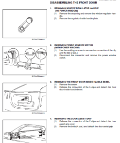
- Offers step-by-step guidance for repairs to ensure safe and efficient maintenance.
- Helps in identifying potential issues and preventing failures through regular inspections.
- Provides detailed insights and specifications, guaranteeing reliable truck operation.
Usage Recommendations
- Refer to this manual for all repair processes to minimize injury risks and ensure correct procedures.
- Regular maintenance is crucial; adhere to the recommended schedules in the Owners and Drivers Manual.
- Perform inspections regularly to ensure the truck operates smoothly, safely, and economically.
Manual Contents
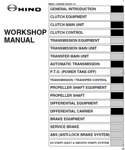
This manual includes detailed sections on:
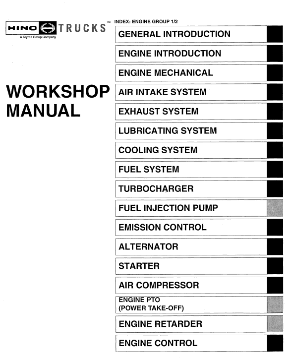
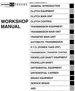
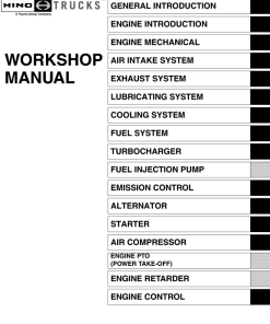
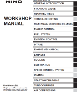
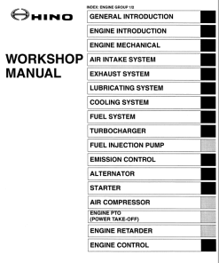
- General Introduction
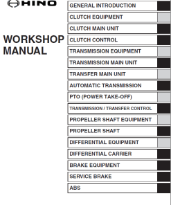
- Clutch Equipment and Control
- Transmission and Transfer Units
- Automatic Transmission and Power Take-Off (P.T.O.)
- Propeller Shaft and Differential Equipment
- Brake Equipment including ABS & ASR Systems
- Exhaust Brake and Steering Equipment
- Front and Rear Axles, Wheels & Tires
- Suspension and Chassis Equipment
Instruction Extract
Hino Truck 2009 Manual Instruction:
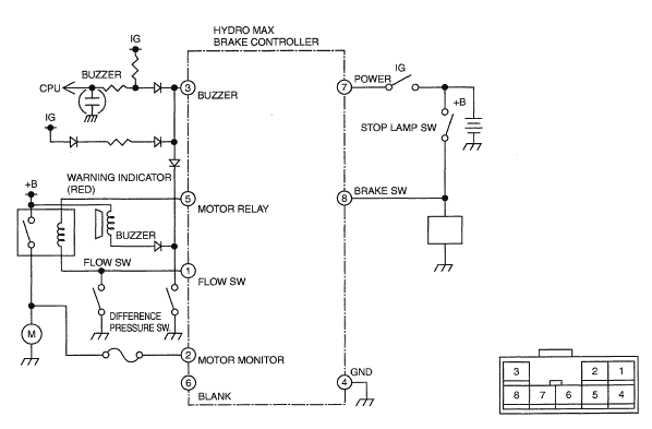
Hydro Max Brake Controller Inspection
- Wire the HYDRO MAX brake controller, buzzer, and motor relay as shown in the figure.
- Check operation:
- When IG is on, an alarm is triggered by motor monitor low voltage.
- An alarm is triggered by high voltage of motor monitor and IG on.
- An alarm is triggered by the opening of the motor monitor circuit and IG on.
- Electric power supplied to the motor relay coil with IG on or brake switch on.
NOTICE: “IG on” means the starter switch is turned on.
Only logged in customers who have purchased this product may leave a review.









Reviews
There are no reviews yet.