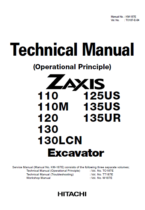
Hitachi ZX125US, ZX135US, ZX135UR Excavator Service Repair Manual
$35.00
Format: PDF
Language: English
Hitachi ZX125US, ZX135US, ZX135UR Excavator Service Manual
Product Overview
This comprehensive service manual is designed for the Hitachi ZX125US, ZX135US, and ZX135UR Excavator models. It serves as an essential resource for the maintenance and troubleshooting of these machines, available in an easily accessible PDF format and written in English.
Key Features
- Parts Catalog – 602 Pages
- Troubleshooting Manual – 477 Pages
- Operation Manual – 318 Pages
- Workshop Manual – 748 Pages
Benefits
- Detailed technical information for effective machine operation and troubleshooting.
- Comprehensive guide to perform maintenance and repairs efficiently.
- Redelivery and delivery guidelines included to ensure smooth operational transitions.
Usage Recommendations
- Utilize the Parts Catalog for component identification and replacements.
- Refer to the Troubleshooting Manual for diagnosing and fixing issues using the exchange inspection method.
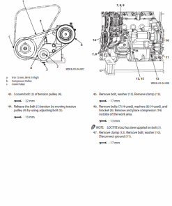
- Consult the Workshop Manual for detailed maintenance procedures and standard servicing protocols.
- Use the Operation Manual to understand the full functionality and operation of the excavator.
Workshop Manual Table of Contents (Excerpt)
This excerpt outlines the structure of the Workshop Manual:
- SECTION 1 GENERAL
- Precautions for Disassembling and Assembling
- Tightening Torque
- Painting
- SECTION 2 UPPERSTRUCTURE
- Cab
- Counterweight
- Main Frame
- Pump Device
- Control Valve
- Swing Device
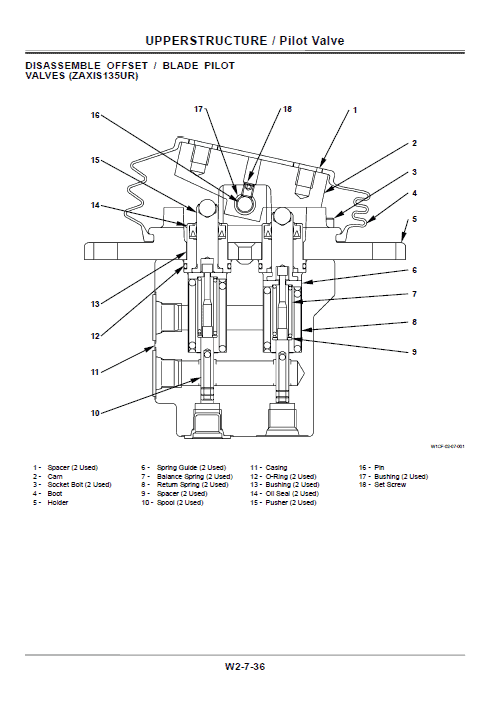
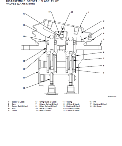
- Pilot Valve
- Pilot Shut-Off Valve
- Signal Control Valve
- Solenoid Valve
- Holding Valve
- SECTION 3 UNDERCARRIAGE
- Swing Bearing
- Travel Device
- Center Joint
- Track Adjuster
- Front Idler
- Upper and Lower Roller
- Track
- SECTION 4 FRONT ATTACHMENT
- Front Attachment
- Cylinder
- SECTION 5 ENGINE
This is only an excerpt from the comprehensive table of contents and not the full table.
Exchange Inspection Method
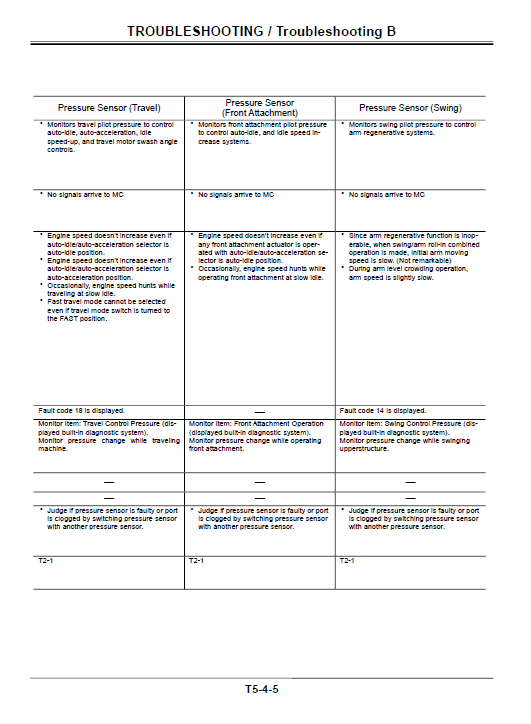
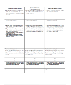
The service manual provides a unique exchange inspection method to effectively locate faults within the ZX125US, ZX135US, and ZX135UR models. This involves swapping parts or components suspected of malfunction with identical working parts, especially useful with similar sensors and solenoid valves.
Example: Diagnosing Abnormal Pump 1 Delivery Pressure (Fault Code: 10)
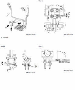
- Switch the two delivery pressure sensors from positions shown in figure A to figure B.
- Repeat the troubleshooting process.
Results:
- If pump 2 delivery pressure becomes abnormal (fault code 11), then the pump 1 sensor is faulty.
- If pump 1 delivery pressure remains abnormal (fault code 10), the pump 1 sensor harness is likely faulty.
Only logged in customers who have purchased this product may leave a review.



Reviews
There are no reviews yet.