Hyundai R450LC-7 Crawler Excavator Service Repair Manual
$35.00
Hyundai R450LC-7 Crawler Excavator Manuals
Explore comprehensive guides for the Hyundai R450LC-7 Crawler Excavator. These manuals are available in English and formatted as PDFs.
Hyundai R450LC-7 Crawler Excavator Service Repair Manual
Product Overview
The Hyundai R450LC-7 Crawler Excavator Service Repair Manual is an essential resource for technicians and service personnel. Written in English and available in PDF format, this comprehensive manual covers all aspects of maintenance and repair for the Hyundai R450LC-7 model. It aims to enhance repair quality by providing detailed guidance and insights into the workings of this powerful excavator.
Visit the Crawler Excavator Model Page
Contents
- Service Repair Manual: 600 Pages
- Operator’s Manual: 192 Pages
Key Features
- Comprehensive coverage of 600 pages detailing repair procedures.
- Additional 192 pages focused on operator instructions.
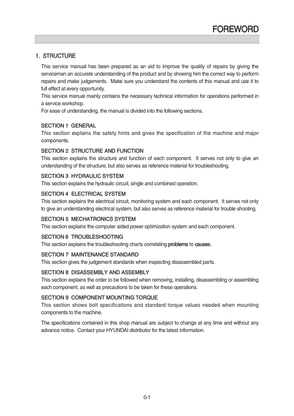
- Sections covering safety, specifications, hydraulic systems, electrical systems, and more.
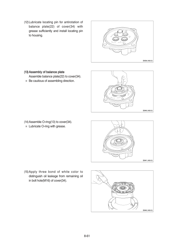
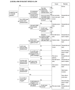
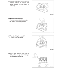
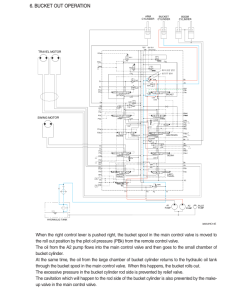
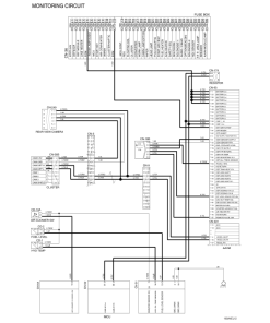
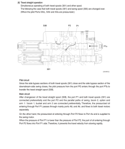
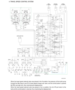
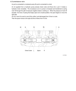
- Illustrations and diagrams for better understanding of components.
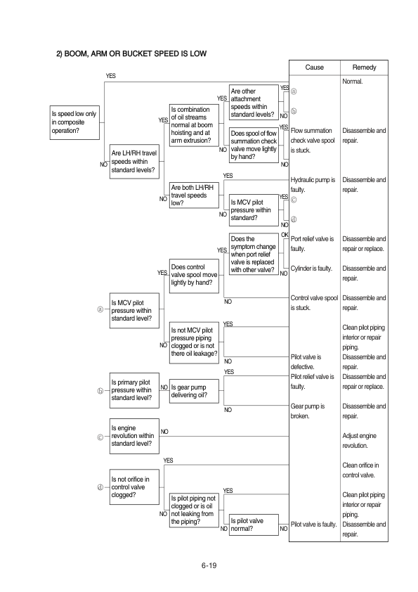
- Up-to-date information on troubleshooting and maintenance standards.
Benefits
- Improves quality of repairs by providing accurate instructions.
- Facilitates better understanding of the excavator’s structure and functions.
- Ensures technicians follow recommended procedures to avoid mistakes.
- Enhances operational efficiency with clear operational guidelines.
Usage Recommendations
- Ideal for use in professional service workshops.
- Recommended for technicians responsible for maintenance and repair.
- Should be used whenever a repair is performed on the Hyundai R450LC-7 model.
- A valuable resource for training and educating new staff members.
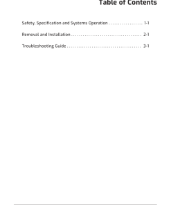
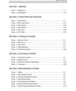
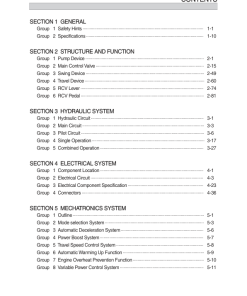
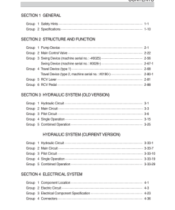
Detailed Table of Contents
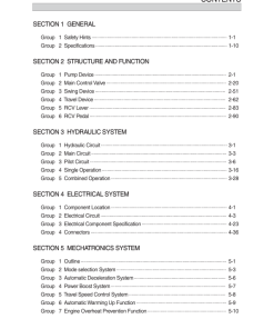
This manual is organized into the following sections, each providing in-depth information and guidance:
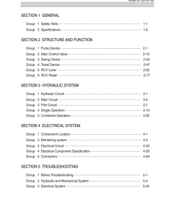
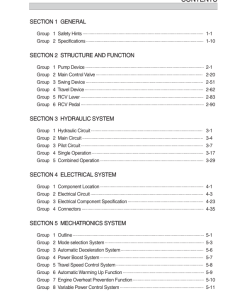
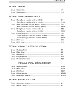
- SECTION 1 GENERAL
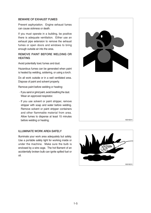
- Group 1: Safety Hints
- Group 2: Specifications
- SECTION 2 STRUCTURE AND FUNCTION
- Group 1: Pump Device
- Group 2: Main Control Valve
- Group 3: Swing Device
- Group 4: Travel Device
- Group 5: RCV Lever
- Group 6: RCV Pedal
- SECTION 3 HYDRAULIC SYSTEM
- Group 1: Hydraulic Circuit
- Group 2: Main Circuit
- Group 3: Pilot Circuit
- Group 4: Single Operation
- Group 5: Combined Operation
- SECTION 4 ELECTRICAL SYSTEM
- Group 1: Component Location
- Group 2: Electrical Circuit
- Group 3: Electrical Component Specification
- Group 4: Connectors
- SECTION 5 MECHATRONICS SYSTEM
- Group 1: Outline
- Group 2: Mode Selection System
- Group 3: Automatic Deceleration System
- Group 4: Power Boost System
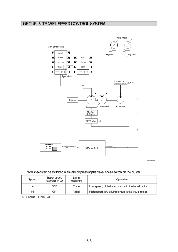
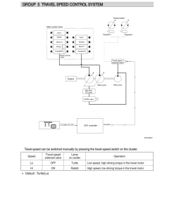
- Group 5: Travel Speed Control System
- Group 6: Automatic Warming-Up Function
- Group 7: Engine Overheat Prevention Function
- Group 8: Anti-Restart System
- Group 9: Self-Diagnostic System
- Group 10: Engine Control System
- Group 11: EPPR (Electro Proportional Pressure Reducing”, “
Only logged in customers who have purchased this product may leave a review.


Reviews
There are no reviews yet.