Komatsu D155A-2 Dozer Service Manual
n
Product Overview
The Komatsu D155A-2 Dozer Service Manual provides vital information and guidelines essential for the servicing and maintenance of your dozer. This comprehensive manual is invaluable for service personnel, containing detailed sections that cover various aspects of maintenance, testing, adjustments, and assembly with an approach designed to enhance the service technicianu2019s understanding and performance.
Key Features
- General Instructions: Comprehensive overview covering essential information and procedures common across different service sections.
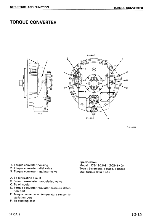
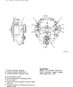
- Structure and Function: Detailed explanations complemented by diagrams of constituent parts, suitable for both servicing and training purposes.
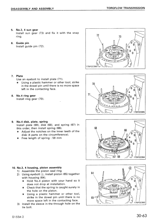
- Testing and Adjustments: Step-by-step procedures illustrated with photographs and accurate measuring equipment locations.
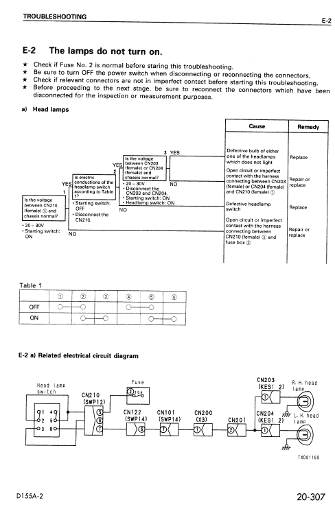
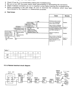
- Troubleshooting: Descriptions of common issues with their causes and troubleshooting procedures, building from foundational knowledge.
- Manual Specifications: Standard dimensions and tolerances required for effective testing, adjustments, and component repair.
Benefits
- Enhances technician proficiency through clear instructions and comprehensive theoretical explanations.
- Assists in accurate diagnosis and repair of mechanical issues with detailed troubleshooting sections.
- Facilitates proper maintenance with precise adjustment and measurement guidelines.
Usage Recommendations
- Ensure thorough understanding of each section to effectively apply the guidelines in real-world scenarios.
- Utilize the u201cStructure and Functionu201d section as a training tool for new service personnel.
- Refer to the troubleshooting section to efficiently address any uncommon mechanical issues that arise.
Adjusting the Spring Assist Brake
Follow these steps to adjust the spring assist brake:
- Check and ensure that both the brake linkage and steering linkage are correctly adjusted.
- Screw in the nut (1) until the rod length “A” reaches 106mm.
- Adjust the nut (3) so that the clearance “B” between the lever (2) and the nut (3) is 0 – 0.5mm.
- Loosen the nut (1) to set the dimension “C” to 36 – 41mm, then secure the position by tightening the locknut (4).
Only logged in customers who have purchased this product may leave a review.
Related products
$34.00
$33.00







Reviews
There are no reviews yet.