Komatsu PC75UU-2 Excavator Service Manual
Product Overview
The Komatsu PC75UU-2 Excavator Service Manual is a comprehensive guide designed to assist in understanding the machine’s specifications, structure, functionality, and maintenance procedures. This manual provides detailed information on maintenance standards, testing methods, and troubleshooting techniques, ensuring that you can efficiently handle and maintain your excavator.
Table of Contents
- 01 General
- 10 Structure and Function
- 20 Testing and Adjusting
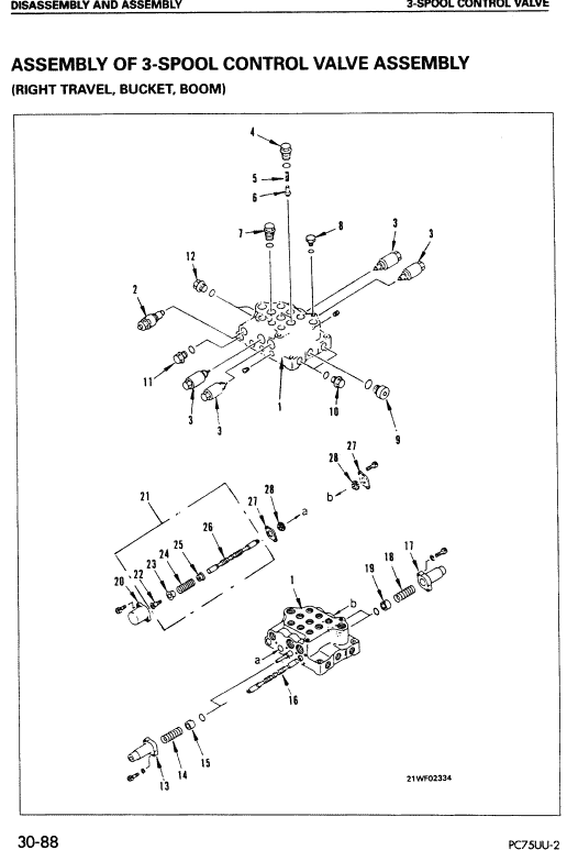
- 30 Disassembly and Assembly
- 40 Maintenance Standard
General Information
This section includes critical information such as the machine’s dimensions, performance specifications, component weights, and specific charts for fuel, coolant, and lubricants. It lays the foundation for understanding your excavator’s general capabilities.
Structure, Function, and Maintenance Standard
Delve into the intricacies of each component’s structure and function. This section not only aids in building a fundamental understanding but also serves as a vital reference for troubleshooting and performing routine maintenance.
Testing, Adjusting, and Troubleshooting
Before and after repairs, essential checks and adjustments are outlined here. Find troubleshooting charts that correlate specific problems with their potential causes, aiding in efficient problem resolution.
Disassembly and Assembly
Komatsu Excavator PC75UU-2
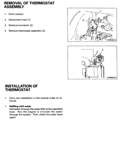
This section provides a step-by-step guide on the proper order for removing, installing, disassembling, and assembling each component. It highlights the safety precautions necessary during these operations to ensure safety and efficiency.
- Use a hoist or crane when lifting heavy components.
- Ensure wire ropes, chains, and hooks are undamaged.
- Use lifting equipment with sufficient capacity.
- Install lifting equipment correctly and operate slowly.
- Never work under a component held by lifting equipment.
Manual Extract
Follow these steps to measure blow-by pressure within safe operating conditions:
- Ensure the coolant and hydraulic oil temperatures are within the standard operating range (45 – 55u00b0C).
- Remove the cylinder head cover (1) and install plug E2 to the breather tube (2).
- Reinstall the cylinder head cover and attach blow-by pressure gauge E1 to the oil filler port.
- Run the engine at rated output to measure the blow-by pressure.
- After testing, remove plug E2.
Note: Blow-by readings can vary based on engine condition. If results seem abnormal, inspect for issues such as excessive oil consumption or defective exhaust gas. For more detailed guidance, click here.
n
Only logged in customers who have purchased this product may leave a review.





Reviews
There are no reviews yet.