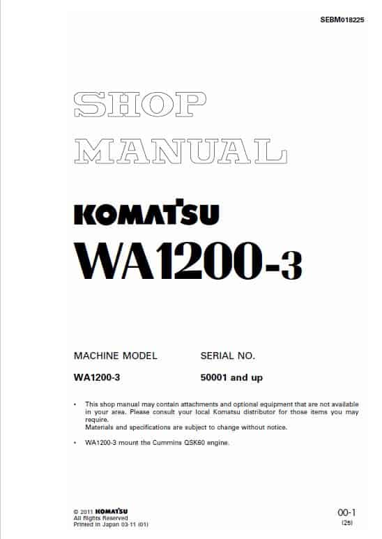
Komatsu WA1200-3 Switching Pump Assembly Removal Guide
Product Overview
Efficiently manage the removal and installation of the switching pump assembly on your Komatsu WA1200-3 machine by following this detailed guide. This procedure ensures proper handling of components and prevents potential damage. Ensure you have all necessary replacement parts on hand, such as hoses and O-rings, as they need to be replaced during reinstallation.
Table of Contents
- 01 General Information
- 10 Structure and Function
- 20 Testing and Adjusting
- 30 Disassembly and Assembly
- 40 Maintenance Standard
- 90 Others
Removal Process
Before commencing with the removal of the switching pump assembly, perform the tasks outlined in “2. Preparatory work” and “3. Precautions during work” of “00-3 Safety Notice” to ensure safe and effective removal.
Step-by-Step Guide
- Drain the hydraulic oil. Volume: Approximately 1,125 liters.
- Open the upper step cover to access internal components.
- Disconnect hoses labeled (1) and (2).
- Proceed to detach hoses (3) and (4).
- Remove U-bolt (5) before disconnecting the suction tube (6).
- Disconnect hose labeled (7).
- Detach hoses (8) and (9).
- Sling the switching pump assembly (10) carefully, remove its mounting bolts, and lift it off.
For reference, here is an image of the switching pump assembly.
Key Features
- Switching pump assembly weighing 190 kg.
- Comprehensive guide for safe disassembly.
- Requirements for replacement of consumable parts.
Benefits
- Ensures smooth removal and installation process.
- Minimizes downtime with detailed step-by-step instructions.
- Prevents potential damage to machinery with careful procedure.
Usage Recommendations
- Always replace consumable parts during the reinstallation process.
- Have all necessary tools and parts ready before starting the procedure.
- Strictly follow precautionary measures for safe handling.
Only logged in customers who have purchased this product may leave a review.
Related products
$32.50
$34.00
$27.50
$34.00











Reviews
There are no reviews yet.