Komatsu Loader WB140PS-2N and WB150PS-2N Service Manual
Product Overview
This comprehensive service manual is designed for the Komatsu Loader models WB140PS-2N and WB150PS-2N. It covers essential maintenance and repair procedures, ensuring your machine remains in optimal working condition. From general specifications to detailed instructions on disassembly and troubleshooting, this manual is an invaluable resource for operators and technicians alike.
Table of Contents
- General
- Engine
- Power Train
- Undercarriage
- Hydraulic System
- Work Equipment
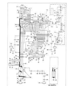
- Electrical System
General
This section presents the overall machine dimensions, performance specifications, and component weights. It also includes essential charts for fuel, coolant, and lubricant specifications to help maintain your equipment efficiently.
Structure, Function, and Maintenance Standard
Explore detailed explanations of each component’s structure and function. This section not only aids in understanding component configurations but also serves as a reliable reference for troubleshooting challenges.
Testing, Adjusting, and Troubleshooting
This portion of the manual provides guidelines on checks to perform before and after repairs. It includes instructions on necessary adjustments and comprehensive troubleshooting charts linking problems to their potential causes.
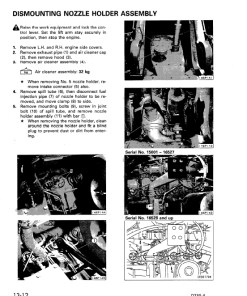
Disassembly and Assembly
This crucial section guides you through the process of removing, installing, disassembling, or reassembling each component. It emphasizes the necessary precautions to take during these operations to ensure safety and success.
For instance, when removing covers that are under internal pressure or spring tension, retain two bolts on opposite sides, gradually release the pressure, then slowly loosen the bolts for safe removal.
Front Bucket Tilt Cylinders for Komatsu WB140PS-2N and WB150PS-2N
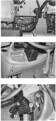
- Loosen the clips and remove the tube protection. For the right-hand cylinder, disconnect the sensor and remove the bucket position rod.
- Support the cylinder with a sling; insert a block between the spacer of the piston fulcrum lever and the link.
- Remove the snap ring and the internal retaining spacer of the piston attachment pin.
- Extract the pin.
- Start the engine to retract the piston, securing the position with wire, then stop the engine.
Only logged in customers who have purchased this product may leave a review.





Reviews
There are no reviews yet.