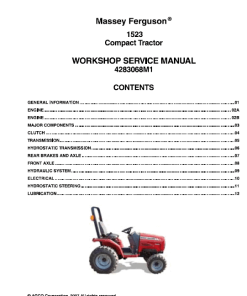
Massey Ferguson 431, 461 Tractors (Turkey) Manual
Product Overview
The Massey Ferguson Tractor workshop service manual is an essential resource for owners and technicians working with the Massey Ferguson 431 and 461 models. Available in PDF format and written in English, this detailed guide is identified by publication number 4283017.
The manual comprises 334 pages focused on the tractors, with an additional 508 pages dedicated to the Perkins Engine 1103 Series.
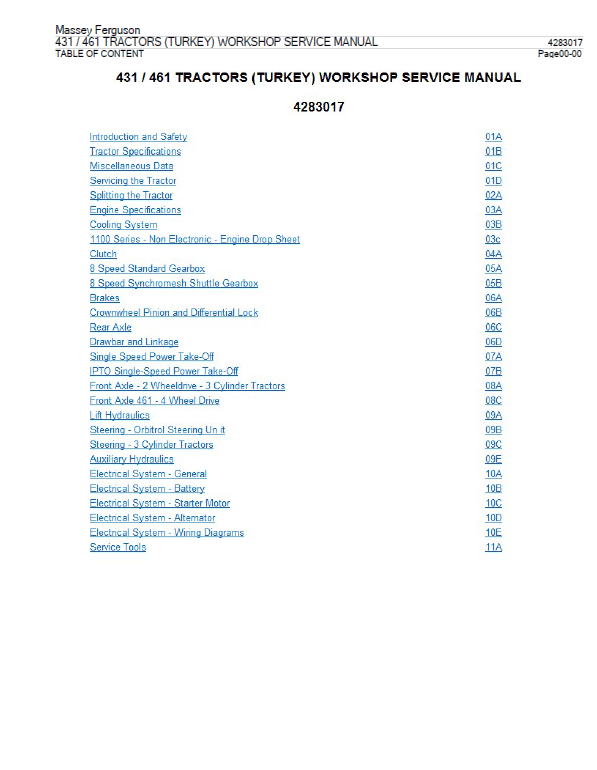
Table of Contents
- Introduction and Safety
- Tractor Specification
- Miscellaneous Data
- Servicing the Tractor
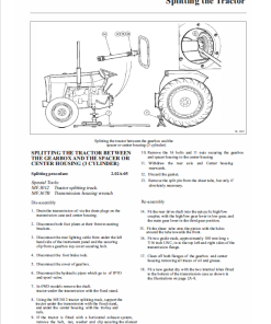
- Splitting the Tractor
- Engine Specification
- Cooling System
- 1100 Series Non-Electronic Engine Drop Sheet
- Clutch
- 8 Speed Standard Gearbox
- 8 Speed Synchromesh Shuttle Gearbox
- Brakes
- Crownwheel Pinion and Differential Lock
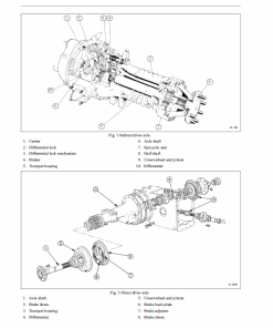
- Rear Axle
- Drawbar and Linkage
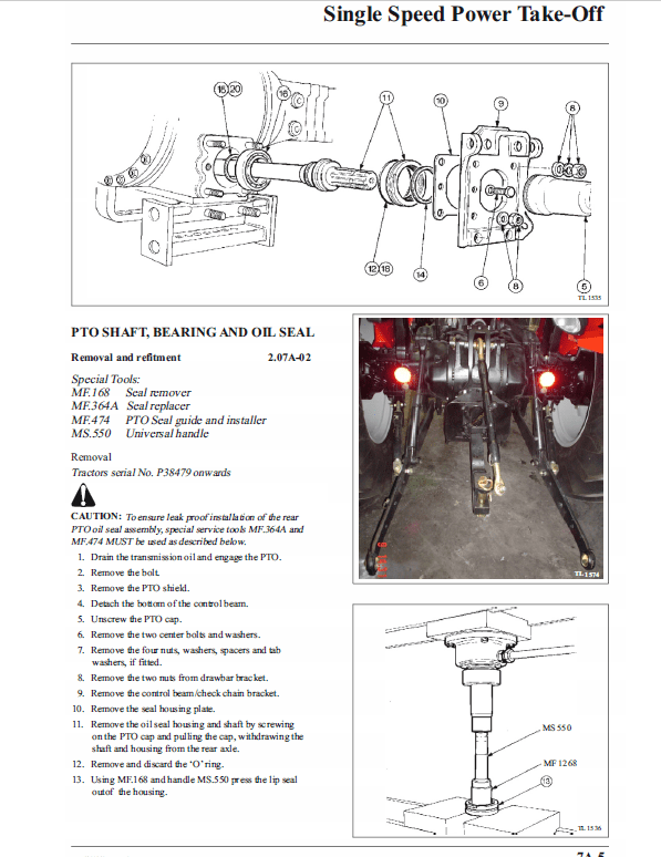
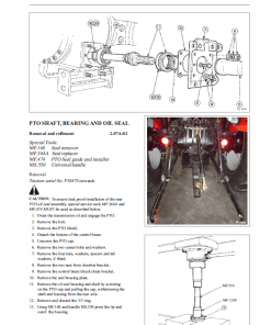
- Single Speed Power Take Off
- IPTO Single Speed Power Take Off
- Front Axle – 2 Wheel Drive – 3 Cylinder Tractors
- Front Axle 461 – 4 Wheel Drive
- Lift Hydraulics
- Steering – Orbital Steering Unit
- Steering 3 Cylinder Tractors
- Auxiliary Hydraulics
- Electrical System
- Service Tools
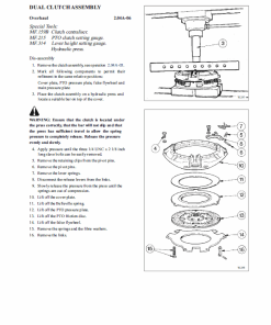
Excerpts: Hydraulic Lift Cylinder
Special Tools
- MF420 Piston Seal Replacer (79 mm)
- MF453 Piston Seal Replacer (94 mm)
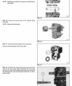
Disassembly Instructions
- Remove the lift cylinder assembly by following operation 2.09A-04, steps 1 to 11.
- Take out the two bolts.
- Detach the support bracket.
- Withdraw the piston from the cylinder.
- Remove the piston seal and ‘O’ ring if required. Inspect all components for wear or damage and replace any defective parts.
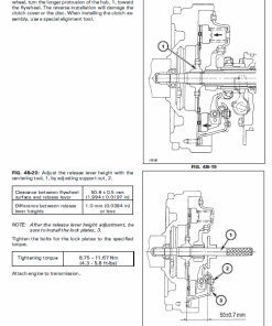
Reassembly Instructions
- If piston seals have been removed, apply transmission oil to the ‘O’ ring part of the seal and fit it into the piston groove.
- Lubricate the outside of the tapered guide with mineral oil (MF.420 for MF.431 tractors, MF.453 for MF.461 tractors). Place the guide on a firm, flat surface. Position the seal on the guide and push it carefully down the taper of the guide until it extends past the end. Position the lip of the seal on the piston at the closed end and press the seal off the guide onto the piston, fitting it into the groove on top of the ‘O’ ring.
- Insert the piston into the wide bore end of the sizing ring, pushing it through until about 12 mm of it extends from the end of the ring.
- Lubricate the bore of the cylinder with transmission oil, then align the protruding portion of the piston with the cylinder bore mouth. Push the piston through the sizing ring into the cylinder.
- Reverse steps 1 to 11 in operation 2.09A-04 to complete the assembly.
Only logged in customers who have purchased this product may leave a review.
Related products
Massey Ferguson
Massey Ferguson 3615, 3625, 3635, 3645 Workshop Service Manual
$19.00 – $36.00
Massey Ferguson
$34.00
Massey Ferguson
$25.00 – $36.00
$27.00 – $38.00
$27.00 – $36.00
Massey Ferguson
$10.00 – $37.00
$34.00
Massey Ferguson
$34.00
Reviews
There are no reviews yet.