Massey Ferguson 6711, 6712, 6713 Tractor Service Manual
$35.00
Total Pages: 1533 (Workshop Manual), 474 (Parts Catalog)
Format: PDF
Language: English
Publication Number: ACT001919A
Massey Ferguson 6711, 6712, 6713 Tractor Manual
Product Overview
The Massey Ferguson MF 6700 Series Tractor manual provides comprehensive guidance for models 6711, 6712, and 6713. This extensive manual, available in PDF format and written in English, is an essential resource for anyone seeking detailed information and instructions about these tractors. The publication number for this manual is ACT001919A.
This manual includes:
- Workshop Manual: 1533 pages
- Parts Catalog: 474 pages
Key Features
- Clear instructions and detailed diagrams for all models within the series.
- Step-by-step procedures for maintenance and repair.
- Access to specific parts and assembly information for precise troubleshooting.
Benefits
- Enables efficient maintenance and repair work.
- Reduces downtime by providing quick solutions to common issues.
- Empowers users with thorough understanding and insights into tractor operation.
Usage Recommendations
- Ideal for technicians, engineers, and dedicated DIY enthusiasts who routinely work with the Massey Ferguson tractors.
- A valuable addition to workshop libraries and personal collections for reference during repairs or part replacement.
Manual Table of Contents
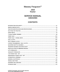
- Introduction
- Separation of assemblies
- Engine
- Clutch
- Gearbox
- Rear axle
- Power Take Off
- Front axle
- Hydraulics
- Electricity
- Electronics
- Operator environment
Detailed Procedure: Removing the Crankshaft
Procedure
- Remove the oil sump.
- Disconnect the lubricating oil pipe of the balancing unit from the cylinder block.
- Loosen the fixing bolts of the balancing unit.
- Remove the balancing unit and the lubricating oil pipe.
- Loosen the fixing screws to remove the pressure pipe of the oil pump from the cylinder block.
- Remove the oil pump and the suction and pressure pipes.
- Remove the flywheel and the crankshaft rear oil seal with housing.
- Remove the belt pulley and the hub from the crankshaft front end.
- Remove the timing gear housing.
- Remove the bearing caps of the connecting rod and push the connecting rods out of the way of the crankshaft.
- Remove the main bearing caps and lift out the crankshaft.
Checking the Crankshaft
Note: When grinding, ensure the journal edges remain round. Additionally, due to automatic assembly, thrust bearings are integrated into the main bearings. Undersize spare part main bearings and thrust bearings are provided separately.
Only logged in customers who have purchased this product may leave a review.
Related products
Massey Ferguson
Massey Ferguson
Massey Ferguson
Massey Ferguson
Massey Ferguson GC1705, GC1710, GC1715, GC1720 Service Manual
Massey Ferguson
Massey Ferguson 3615, 3625, 3635, 3645 Workshop Service Manual
Massey Ferguson












Reviews
There are no reviews yet.