-
×
 Caterpillar CAT CS-683E Vibratory Compactor Service Repair Manual (ASG00001 and up)
$50.00
 -
×
 Kobelco LK450 II Wheel Loader Service Manual
$33.00
 -
×
 Sennebogen 825.0.1338 Operators, Maintenance and Parts Manual
$39.00
 -
×
 New Holland LB90, LB110 Backhoe Loaders Service Manual
$36.00
 -
×
 Caterpillar CAT CS-663E, CP-663E Vibratory Compactor Service Repair Manual (DAF00001 and up)
$50.00
 -
×
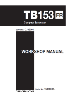 Takeuchi TB153 Compact Excavator Service Manual
$35.00
 -
×
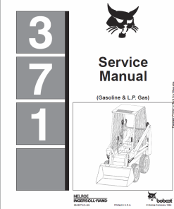 Bobcat 371 Skid-Steer Loader Service Manual
$32.00
 -
×
 New Holland B90B, B95B, B95 BLR, B95 TC Backhoe Loader Service Manual
$34.50
 -
×
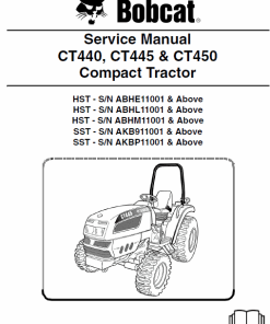 Bobcat CT440, CT445 and CT450 Compact Tractor Service Manual
$36.00
 -
×
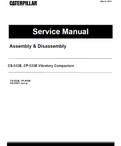 Caterpillar CAT CS-533E, CP-533E Vibratory Compactor Service Repair Manual (ASL00001 and up)
$50.00
 -
×
 Kobelco LK400 Wheel Loader Service Manual
$33.00
 -
×
 Bobcat S185 Skid-Steer Loader Service Manual
$34.00
 -
×
 JCB 801 Tracked Excavator Service Manual
$30.00
 -
×
 Bobcat CT335 Compact Tractor Service Manual
$36.00
 -
×
 JCB Vibromax VM66 Single Drum Roller Service Manual
$26.65
 -
×
 Bobcat 753 and 753HF Skid-Steer Loader Service Manual
$32.00
 -
×
 Bobcat 1213 Skid-Steer Loader Service Manual
$32.00
 -
×
 John Deere 990 Compact Utility Tractors Technical Manual (TM1848)
$30.00
 -
×
 John Deere XUV 620i Gator Utility Vehicle Technical Manual (TM1736)
$39.00
 -
×
 Kobelco LK500 Wheel Loader Service Manual
$32.50
 -
×
 John Deere A3 M-Gator Repair Technical Manual (TM115719)
$38.00
 -
×
 JCB FM25 Mower Service Manual
$30.00
 -
×
 John Deere 860B Scraper Repair Technical Manual (TM1171)
$38.00
 -
×
 Sennebogen 825.0.1151 Operators, Maintenance and Parts Manual
$39.00
 -
×
 Caterpillar CAT 120H Motor Grader Service Repair Manual (5FM00001 and up)
$70.00
 -
×
 John Deere 315SL Backhoe Loader Repair Technical Manual (S.N F273920 - F390995)
$60.00
 -
×
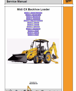 JCB Midi CX Backhoe Loader Service Manual
$34.00
 -
×
 John Deere 310SL HL, 410L Backhoe Loader Repair Technical Manual (S.N after F390996 - )
$57.00
 -
×
 Bobcat T300 Loader Service Manual
$35.00
 -
×
 John Deere XUV590i, XUV590i S4 Gator Utility Vehicles Repair Technical Manual
$46.00
 -
×
 Bobcat S175 Skid-Steer Loader Service Manual
$35.00
 -
×
 Sennebogen 305.0.398 (305 C+ & 305 XL) Operators, Maintenance and Parts Manual
$38.00
 -
×
 Bobcat B780 Loader Service Repair Manual
$38.00
 -
×
 Bobcat X337 and X341 Excavator Service Manual
$29.00
 -
×
 Kobelco LK600A Wheel Loader Service Manual
$32.50
 -
×
 Caterpillar CAT 14G Motor Grader Service Repair Manual (96U00001 till 01097)
$70.00
 -
×
 Bobcat E26 Excavator Repair Service Manual
$38.00
 -
×
 Bobcat BL470, BL475 Loader Service Repair Manual
$38.00
 -
×
 Caterpillar CAT 140M Motor Grader Service Repair Manual (B9M00001 and up)
$65.00
Product Maintenance Manual
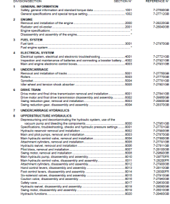
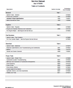
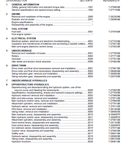
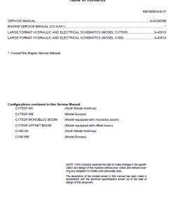
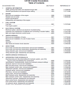
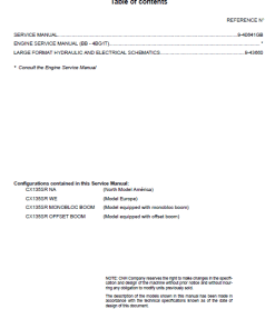
Table of Contents
- Content Overview
- Introduction
- Engine
- Hydraulics System
- Frames and Ballasting
- Tracks and Track Suspension
- Electrical System
- Booms, Dippers, and Buckets
- Dozer Blade and Arm
- Platform, Cab, Bodywork, and Decals
- Special Tools Index
- Electrical Schematic
- Hydraulic Schematic
Manual Extract: Camshaft Alignment
Step-by-step Guide:
-
Support the camshaft using V-blocks placed at both end journals on the surface plate.
-
Position a dial indicator with the tip touching the intermediate journal.
-
Measure the camshaft’s alignment accurately.
-
If the measure exceeds the allowable limit, it is necessary to replace the camshaft.
Technical Specifications
- Camshaft Alignment: Ensure alignment does not exceed the limit of 0.01 mm (0.0004 in).
-
Cam Height Measurement:
- Measure the highest point of the cam using an outside micrometer.
- If the cam height is below the allowable limit, replace the camshaft.
- Factory Specification: 26.88 mm (1.058 in)
- Allowable Limit: 26.83 mm (1.056 in)
Only logged in customers who have purchased this product may leave a review.
Related products
$33.00
$32.00
$32.00
$35.00
$34.00
$34.00
$34.50



Reviews
There are no reviews yet.