-
×
 Caterpillar CAT CS-683E Vibratory Compactor Service Repair Manual (ASG00001 and up)
$50.00
 -
×
 Kobelco LK450 II Wheel Loader Service Manual
$33.00
 -
×
 Sennebogen 825.0.1338 Operators, Maintenance and Parts Manual
$39.00
 -
×
 New Holland LB90, LB110 Backhoe Loaders Service Manual
$36.00
 -
×
 Caterpillar CAT CS-663E, CP-663E Vibratory Compactor Service Repair Manual (DAF00001 and up)
$50.00
 -
×
 Takeuchi TB153 Compact Excavator Service Manual
$35.00
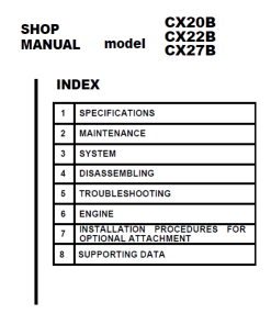
Service Manual: Comprehensive Guide
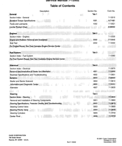
Table of Contents
- Content Overview
- Introduction
- Engine
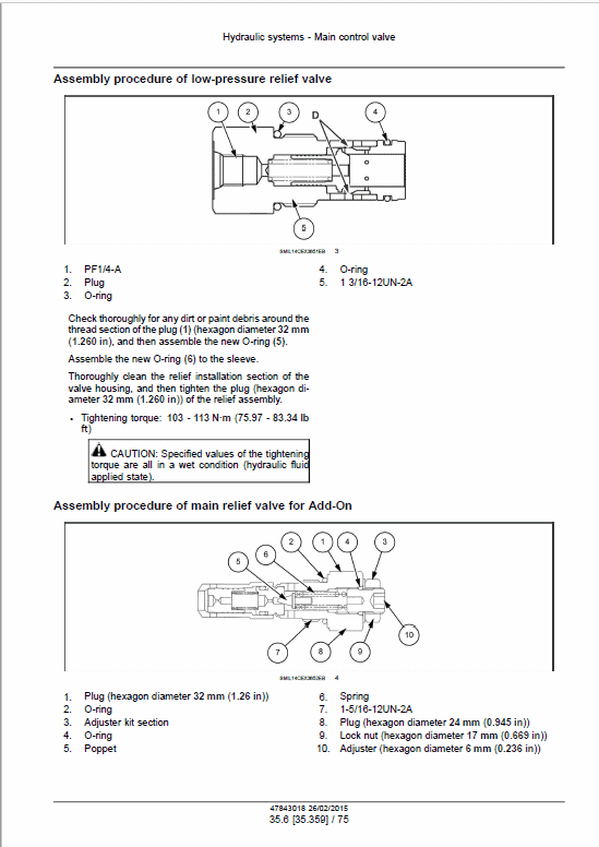
- Hydraulics System
- Frames and Ballasting
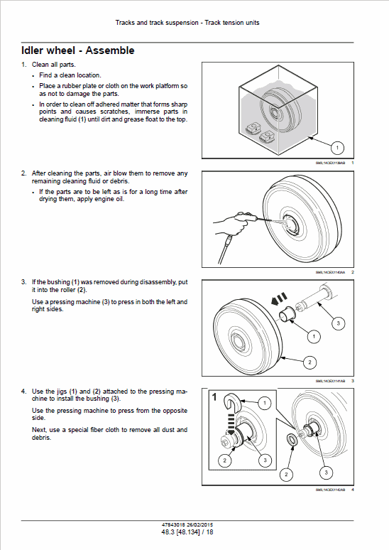
- Tracks and Track Suspension
- Cab Climate Control
- Electrical System
- Booms, Dippers, and Buckets
- Dozer Blade and Arm
- Platform, Cab, Bodywork and Decals
- Special Tools Index
- Hydraulic Schematics
- Electrical Schematics
Alternator – Static Description
The primary components of the charging system in focus are:
- The battery
- The generator
- The battery discharge indicator light circuit
The generator is a self-rectifying model with an integrated regulator.
Generator Details
The generator is designed as a brushless type, featuring several key components:
- Rotor and Stator
- Rectifier Assembly
- Front and Rear Brackets
- IC Regulator
- Bearings
- Pulley
The rotor and pulley are essential moving parts, while the field coil is securely attached to the rear bracket. To convert the three-phase alternating current, generated in the stator coil, into direct current, the system uses:
- Six main diodes (including positive and negative diodes)
- Three supplementary diodes referred to as the trio diode
These diodes play a crucial role in supplying field current.
Connection Terminals
This generator includes three terminals:
- B Terminal: Direct current output terminal
- L Terminal: Functions as both input and output terminal, thus allowing initial excitation current until power generation starts
- R Terminal: Supports initial current excitation
When the voltage at the L terminal aligns with the battery voltage, the charge indicator light switches off. Both bearings are sealed, removing the need for periodic lubrication.
Note: The IC regulator is non-disassemblable and should be serviced as a complete unit.
Only logged in customers who have purchased this product may leave a review.
Related products
$34.00
$35.00
$34.00
$34.00
$34.00
$33.00




Reviews
There are no reviews yet.