Doosan DX180LC-3 Excavator Service Manual
$34.50
Enhance your maintenance and repair skills with the comprehensive Doosan DX180LC-3 Excavator Service Repair Manual. Covering 882 pages, this manual is available in PDF format and is written in English. It is designed for models with serial numbers 50001 and up.
Publication Number: 950106-00417E
Doosan DX180LC-3 Excavator Service Manual
Product Overview
The Doosan DX180LC-3 Excavator Service Manual is an essential PDF resource for maintaining and servicing the Doosan DX180LC-3 excavator model. This comprehensive manual is published in English, comprising 882 pages of detailed instructions and illustrations. It covers all units bearing the serial number 50001 and up under publication number 950106-00417E.
Key Features
- Detailed service procedures with step-by-step guidance.
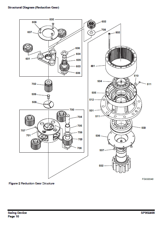
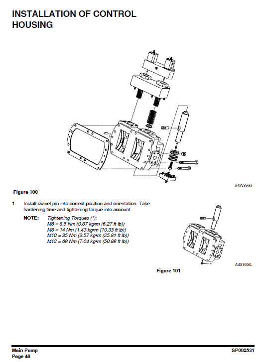
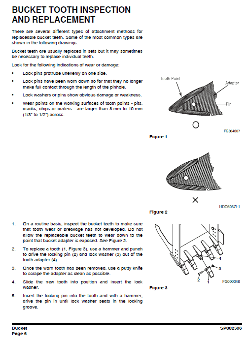
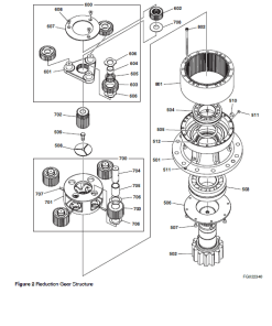
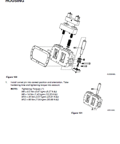
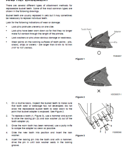
- High-quality photographs and drawings for easy component identification.
- In-depth troubleshooting and repair schematics for major engine systems.
- Comprehensive safety information to ensure proper care and handling.
- Appendices including specifications, standard torques, and electrical schematics.
Benefits
- Enhances your ability to conduct routine maintenance and complex repairs.
- Improves efficiency by providing clear instructions and visual aids.
- Increases safety awareness with detailed precautions and illustrated warning labels.
- Streamlines troubleshooting with logical sequences and systematic layouts.
Usage Recommendations
- Regularly review safety sections before operating or servicing the excavator.
- Utilize the table of contents for quick access to desired service procedures.
- Conduct frequent inspections of critical components to prevent premature wear.
- Follow specific testing procedures for diagnosing system issues effectively.
DOOSAN DX180LC-3 Table of Contents
This manual includes sections on:
- Safety: Comprehensive guidelines and track excavator maintenance safety.
- Specifications: Detailed specifications aligned with the DX180LC-3 model.
- General Maintenance: General maintenance instructions and standard torques.
- Upper Structure: Cabin, counterweight, fuel system, and swing bearing details.
- Lower Structure and Chassis: Information about the track assembly.
- Engine and Drivetrain: Features components such as the coolant heater and drive coupling.
- Hydraulics: Includes troubleshooting, testing, adjustment, and hydraulic schematics.
- Electrical System: Pertinent electrical system and schematic data.
- Attachments: Information on boom, arm, and bucket configurations.
Manual Instruction Extract
Troubleshooting, Testing, and Adjustment
Inspection
Inspect the center joint every 2,000 operating hours for external oil leakage, indicative of potential contamination and accelerated wear. Address any leakage by repairing or replacing worn components.
Testing
To test the pressure through the center joint, assemble a test kit using:
- 700 bar (10,000 psi) pressure gauge.
- Adapters, connectors, and piping conforming to high-pressure connections.
- A high-pressure relief valve with a setting 1.5 times the system’s maximum pressure.
- Stop and changeover valves for manipulating the testing flow.
Use this kit to pressurize the joint above normal working conditions and perform a leak down test by manually securing the stop valve.
NOTE: You can also configure a similar test kit for the drain port side of the center joint using suitable piping and connectors.
Only logged in customers who have purchased this product may leave a review.

 Doosan DX27Z Excavator Service Manual
  Volvo ABG3870 Pavers Repair Service Manual
  Hyster S25XM, S30XM, S35XM, S40XMS Diesel & LPG Forklift Truck C010 Series Repair Manual (USA)
  Volvo Paver Controls Pavers Repair Service Manual
Reviews
There are no reviews yet.