-
×
 Volvo EC290B LR Excavator Repair Service Manual
$59.00
 -
×
 Volvo EC220E LS Excavator Repair Service Manual
$55.00
 -
×
 Volvo EC210C LR Excavator Repair Service Manual
$59.00
 -
×
 Volvo EC350D Excavator Repair Service Manual
$55.00
 -
×
 Doosan Daewoo DX480LC, DX520LC Excavator Service Manual
$35.50
 -
×
 Volvo P2870D Pavers Repair Service Manual
$50.00
 -
×
 Volvo EC380E LHDS Excavator Repair Service Manual
$59.00
 -
×
 Doosan Daewoo DX225LC Excavator Service Manual
$34.00
 -
×
 Doosan DX340LC-3 and DX350LC-3 Excavator Service Manual
$35.00
 -
×
 Volvo EC500E LHBS Excavator Repair Service Manual
$59.00
 -
×
 Volvo EC750D L Excavator Repair Service Manual
$59.00
 -
×
 Volvo EW200B Excavator Repair Service Manual
$50.00
 -
×
 Doosan DX235NLC-5 Excavator Service Manual
$35.00
 -
×
 Doosan DX380LC-5 Excavator Service Manual
$35.00
 -
×
 Volvo EC210D Excavator Repair Service Manual
$59.00
 -
×
 Doosan Daewoo Solar S470LC-V Excavator Service Manual
$34.00
Doosan DX380LC-3 Excavator Service Manual
Product Overview
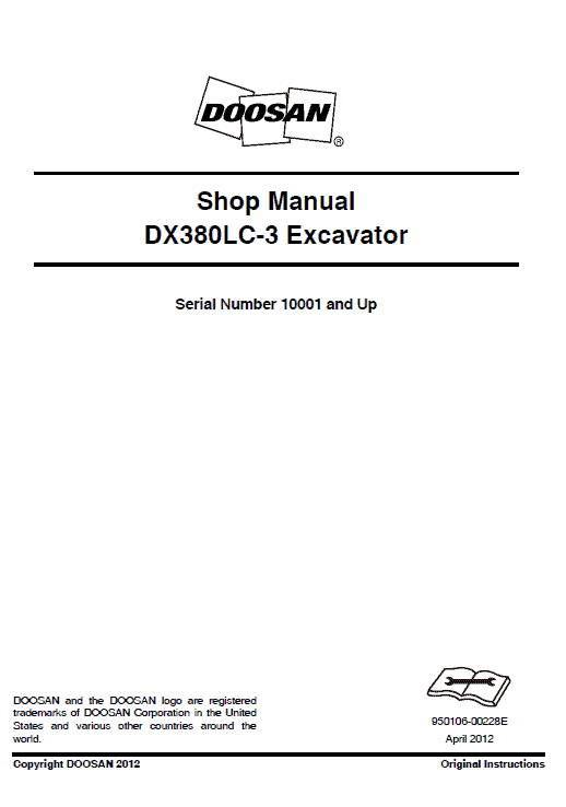
The Doosan DX380LC-3 Excavator Service Manual is an essential guide for maintaining and repairing your excavator. This comprehensive manual includes 976 pages of detailed instructions, illustrations, and safety information. Designed in PDF format and available in English, it is suitable for excavators with Serial Number 10001 and above. The Publication Number is 950106-00228E.
Key Features
- Detailed service procedures with step-by-step instructions.
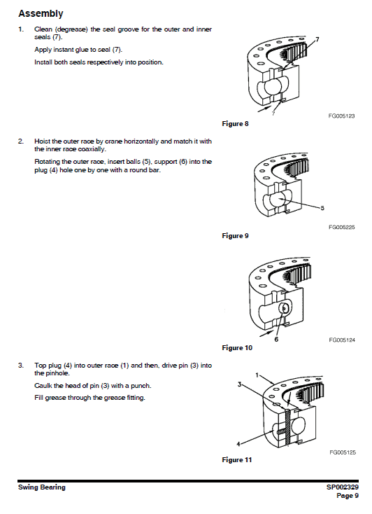
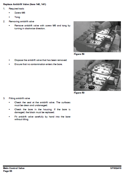
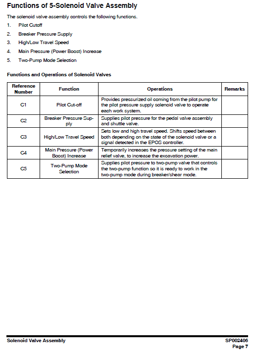
- Includes both photographs and drawings for easier understanding.
- Comprehensive table of contents for quick service procedure access.
- Schematic representations of major engine systems for troubleshooting.
Benefits
- Ensures proper maintenance and repair of the Doosan DX380LC-3 Excavator.
- Improves safety with detailed precautions and warning labels.
- Provides thorough guidance on troubleshooting and component identification.
Usage Recommendations
- Follow the precautions in the Safety section to ensure safe operations.
- Utilize the table of contents for efficient navigation through the manual.
- Be vigilant with WARNING labels and specific hazard instructions.
Instruction Table of Contents
The manual is structured into several sections, detailing various parts and systems of the excavator. Some key areas covered include:
- Safety – Track Excavator Maintenance Safety: SP002322
- Specifications – Specification for DX380LC-3: SP002604
- General Maintenance – Standard Torques: SP002404
- Upper Structure – Cabin: SP002324
- Lower Structure and Chassis – Track Assembly: SP002607
- Hydraulics – Hydraulic System Troubleshooting: SP002412
- Electrical System – Electrical Schematic: SP002419
- Attachments – Boom and Arm: SP002605
Changing the Burner Head
Removal:
- Remove the heater.
- Detach the combustion air fan.
- Disconnect the burner, flame monitor, and glow plug.
- Remove the mounting screw of the V-clamping collar (Figure 6, Item 2) and pull off the collar.
- Extract the burner head (Figure 6, Item 1) from the heat exchanger (Figure 6, Item 3).
- Complete necessary tasks on disassembled components.
Installation:
Note: The burner head and exhaust outlet port can be aligned during installation.
- Carefully guide the burner head into the heat exchanger, align, and secure with the V-clamping collar.
- Tighten the V-clamping collar mounting screw to 3 Nm u00b110% if needed.
- Reconnect the burner, flame monitor, and glow plug.
- Reattach the combustion air fan.
- Reinstall the heater.
Only logged in customers who have purchased this product may leave a review.
Related products
$35.00
$35.50
$34.00
$34.00
$34.00
$34.00






Reviews
There are no reviews yet.