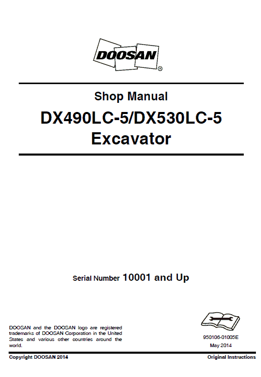
Doosan DX490LC-5 and DX530LC-5 Excavator Service Manual
$35.00
Format: PDF
Language: English
Publication No: 950106-01005E
Serial Number: 10001 and Up
This comprehensive 1580-page manual is an essential guide for servicing and repairing Doosan DX490LC-5 and DX530LC-5 excavators.
Doosan DX490LC-5 and DX530LC-5 Excavator Service Manual
Product Overview
The Doosan DX490LC-5 and DX530LC-5 Excavator Service Manual provides comprehensive guidance on servicing and maintaining these robust and efficient excavators. With 1580 detailed pages, this manual is an essential resource for equipment operators and service technicians.
Format: PDF
Language: English
Publication No: 950106-01005E
Serial Number: 10001 and Up
Key Features
- Detailed sectional breakdown with clear, step-by-step service instructions.
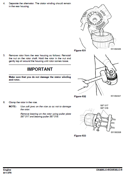
- Inclusion of high-quality photographs and drawings for component identification.
- Structured to guide users through recommended service sequences effectively.
- Comprehensive schematics for engine system troubleshooting and repairs.
Benefits
- Enhances equipment longevity through regular, correct maintenance.
- Reduces downtime with precise troubleshooting and repair procedures.
- Improves safety by providing thorough safety precautions and warnings.
- Facilitates easy navigation to needed sections via a detailed table of contents.
Usage Recommendations
- Always begin by consulting the safety instructions to prevent accidents.
- Use the table of contents to quickly locate necessary procedures.
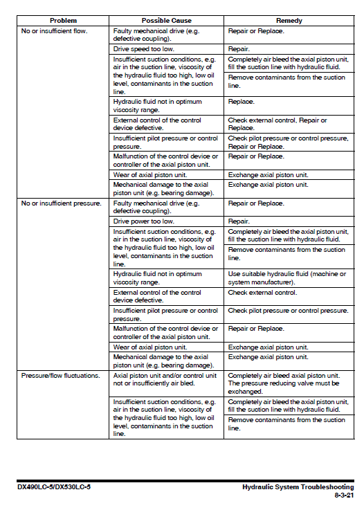
- Refer to the troubleshooting section for resolving specific system issues.
- Follow the sequential steps outlined to ensure effective servicing.
Instruction Table of Content
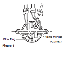
Example Procedure: Changing the Burner, Flame Monitor, and Glow Plug Removal
Removal Steps
- Remove the heater.
- Remove the combustion air fan.
- Remove the screw (5, Figure 5) and washer (4, Figure 5).
- Remove the nuts (10, Figure 5) and pull off the bar (8, Figure 5).
- Extract the grommets (11 and 12, Figure 5) from the combustion pipe’s housing (3, Figure 5).
- Remove the grommet (13, Figure 5) and burner (1, Figure 5) with the swirl orifice (2, Figure 5).
- Take out the flame monitor (7, Figure 5) and glow plug (6, Figure 5).
- Visually assess the burner for defects.
- Complete necessary work on the dismantled components.
Installation Steps
- Place the swirl orifice (2, Figure 5) onto the burner (1, Figure 5).
- Insert the flame monitor (7, Figure 5) and glow plug (6, Figure 5) into the burner securely, and replace the grommets (11 and 12, Figure 5).
- Install the burner (1, Figure 5) and grommet (13, Figure 5) back into the burner head (3, Figure 5).
- Attach the insulation (9, Figure 5) onto the bar (8, Figure 5) and reposition the bar.
- Secure the bar with nuts (10, Figure 5) tightening them to 3 N.m u00b1 10%.
- Fasten the fuel line with the screw (5, Figure 5) and washer (4, Figure 5), and tighten to 3 N.m u00b1 10%.
- Reinstall the combustion air fan.
- Reconnect all electrical connections.
- Replace the heater.
Only logged in customers who have purchased this product may leave a review.
Related products
$34.00
$34.00
$34.00
$34.00
$31.00
$34.00

 Volvo A30F Articulated Dump Truck Repair Service Manual (SN 12001-99999)





Reviews
There are no reviews yet.