-
×
 Caterpillar CAT D5K2 XL Track-Type Tractor Service Repair Manual (WT300001 and up)
$70.00
 -
×
 Komatsu 930E-4SE Dump Truck Service Repair Manual
$44.00
 -
×
 New Holland EH215 Crawler Excavator Service Manual
$35.00
 -
×
 Komatsu WA450-2 Wheel Loader Service Manual
$35.00
 -
×
 New Holland T14.90 RS, T14.100 RS Tractor Service Manual
$35.50
 -
×
 Case 780D Loader Backhoe Service Manual
$35.00
 -
×
 Iveco F4BE0484E, F4BE0684D and F4BE0684B Engines Service Manual
$25.00
 -
×
 Ford 830, 1130 Rider Mower Tractor Service Manual
$20.00
 -
×
 Case Farmall 55C, 65C, 75C Tractor Service Manual
$34.00
 -
×
 Yanmar B95W Wheeled Excavator Service Repair Manual
$40.00
 -
×
 Caterpillar CAT D5K XL Track-Type Tractor Service Repair Manual (WWW00001 and up)
$70.00
 -
×
 Kubota B2301, B2601 Tractor Workshop Service Manual
$34.00
 -
×
 Komatsu 3D82AE, 3D84E, 3D88E Series Engine Manual
$26.00
 -
×
 Komatsu D575A-2 Dozer Service Manual
$35.00
 -
×
 Caterpillar CAT D6H Track Type Tractor Service Repair Manual (8KB00001 and up)
$70.00
 -
×
 Volvo SD160DX Soil Compactor Repair Service Manual
$27.00
 -
×
 New Holland W230C Wheel Loader Service Manual
$34.00
 -
×
 Caterpillar CAT AP-255E Asphalt Paver Service Repair Manual (D8A00001 and up)
$70.00
 -
×
 New Holland TC40DA, TC45A, TC45DA Tractor Service Manual
$35.00
 -
×
 Komatsu PC100-6, PC120-6, PC120LC-6, PC130-6 Excavator Manual
$35.00
 -
×
 Case 9060B Excavator Service Manual
$34.00
 -
×
 Case 580 Super K Backhoe Loader Repair Service Manual
$34.00
 -
×
 Liebherr LH40M, LH40C, LH50M Timber, LH50M Tier 4i Excavator Service Manual
$36.00
 -
×
 Caterpillar CAT D11 Track-Type Tractor Service Repair Manual (TKN00001 and up)
$70.00
 -
×
 Hitachi ZW180 Wheel Loader Service Repair Manual
$36.00
 -
×
 Caterpillar CAT CS-573E, CP-573E Vibratory Compactor Service Repair Manual (CNN00001 and up)
$55.00
 -
×
 New Holland MZ14H, MZ16H, MZ18H Mower Tractor Service Manual
$24.00
 -
×
 Komatsu D21A-8E0 and D21P-8E0 Dozer Service Manual
$34.00
 -
×
 Caterpillar CAT CB-534D Vibratory Compactor Service Repair Manual (EAA00001 and up)
$50.00
 -
×
 New Holland T4030N, T4040N, T4050N, T4060N Tractor Service Manual
$37.00
 -
×
 Komatsu WA320-5, WA320-5H Wheel Loader Service Manual
$35.00
 -
×
 Komatsu WA380-6 Wheel Loader Service Manual
$35.00
 -
×
 Caterpillar CAT D5R2 Track-Type Tractor Service Repair Manual (R5A00001 and up)
$70.00
 -
×
 Hitachi ZX200, ZX225USR, ZX230 and ZX270 ZAXIS Excavator Repair Manual
$37.00
 -
×
 Liebherr D856 A7 Engine Service Manual
$34.00
 -
×
 New Holland LM1060 Telehandlers Service Manual
$33.00
 -
×
 Komatsu D39EX-21, D39PX-21 Dozer Service Manual
$35.00
 -
×
 New Holland E245C Evo Excavator Service Manual
$37.00
 -
×
 Komatsu WB150AWS-2N Backhoe Loader Service Manual
$34.00
 -
×
 Komatsu D21A-8 and D21P-8 Dozer Service Manual
$34.00
 -
×
 Komatsu WA800-1, WA800-2 Wheel Loader Service Manual
$34.00
 -
×
 New Holland EH30.B, EH35.B Excavator Service Manual
$34.00
 -
×
 New Holland E80B Tier 4 Excavator Service Manual
$33.00
 -
×
 Case 1470 Traction King Tractor Service Manual
$30.00
 -
×
 Caterpillar CAT D5K2 LGP Track-Type Tractor Service Repair Manual (KYY00001 and up)
$70.00
 -
×
 New Holland LS180.B, LS185.B and LS190.B SkidSteer Service Manual
$34.00
 -
×
 New Holland T4.55, T4.65, T4.75 Tractor Service Manual
$38.00
 -
×
 John Deere E130, E140LC Excavator Repair Technical Manual (SN. after D300003 - )
$58.00
 -
×
 Case 680B, 680C Loader Service Manual
$34.00
 -
×
 Caterpillar CAT D6G Track-Type Tractor Service Repair Manual (BWJ00001 and up)
$70.00
 -
×
 Case CX210, CX230 and CX240 Excavator Service Manual
$33.00
 -
×
 Caterpillar CAT CS-433E, CP-433E Vibratory Compactor Service Repair Manual (DAC00001 and up)
$50.00
 -
×
 Caterpillar CAT D5B Track-Type Tractor Service Repair Manual (46X00001 and up)
$70.00
 -
×
 Hino Truck 2017 COE HEV Service Manual
$36.00
 -
×
 Caterpillar CAT D4D Track-Type Tractor Service Repair Manual (44H00001 and up)
$70.00
 -
×
 Ford New Holland 555E, 575E, 655E, 675E Backhoe Loader Service Manual
$36.00
 -
×
 New Holland E27B Compact Excavator Service Manual
$34.00
 -
×
 New Holland WE170B, WE190B Wheeled Excavator Service Manual
$34.00
 -
×
 New Holland E30, E35 Compact Excavator Service Manual
$33.00
 -
×
 New Holland E16 and E18 Mini Excavator Service Manual
$34.00
 -
×
 New Holland W110, W130 Wheel Loader Service Manual
$34.00
 -
×
 Case CX290D Crawler Excavator Service Manual
$37.00
Hino Truck FA4J, FB4J Year 2003 Repair Manual (FA, FB)
$36.00
The comprehensive Hino Truck 2003 FA and FB Series Repair and Service Manual is available in PDF format and in English. It is an essential guide for maintaining and servicing your Hino Truck.
SKU: 526639
Category: Hino
Hino Truck FA4J, FB4J Year 2003 Repair Manual
Product Overview
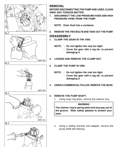
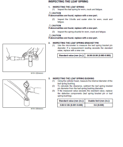
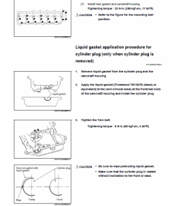
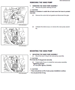
The Hino Truck 2003 Repair and Service Manual is an essential resource for owners and technicians working on the FA and FB series trucks. This comprehensive guide is presented in a convenient PDF format, available in English, and encompasses detailed procedures for various repairs and maintenance tasks.
Key Features
- Complete Repair Manual spanning 1104 pages for the Hino 2003 Truck FA and FB Series.
- Includes the 330-page Hino Truck 2003 Owners Manual.
Benefits
- Ensures smooth, safe, and economical operation of your Hino 2003 trucks.
- Comprehensive coverage of repair procedures helps prevent improper handling that could lead to injury.
- Contains the latest specifications and product information available at the time of printing.
Usage Recommendations
- Regular inspections and maintenance must be performed as specified to ensure optimal performance.
- Refer to the Owners and Drivers Manual for detailed maintenance tasks.
- Use the manual as a guide for making recommended repairs safely and effectively.
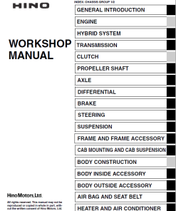
Table of Contents
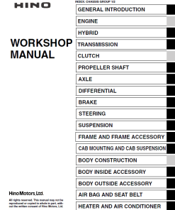
The manual covers a wide range of topics to assist with truck repair:
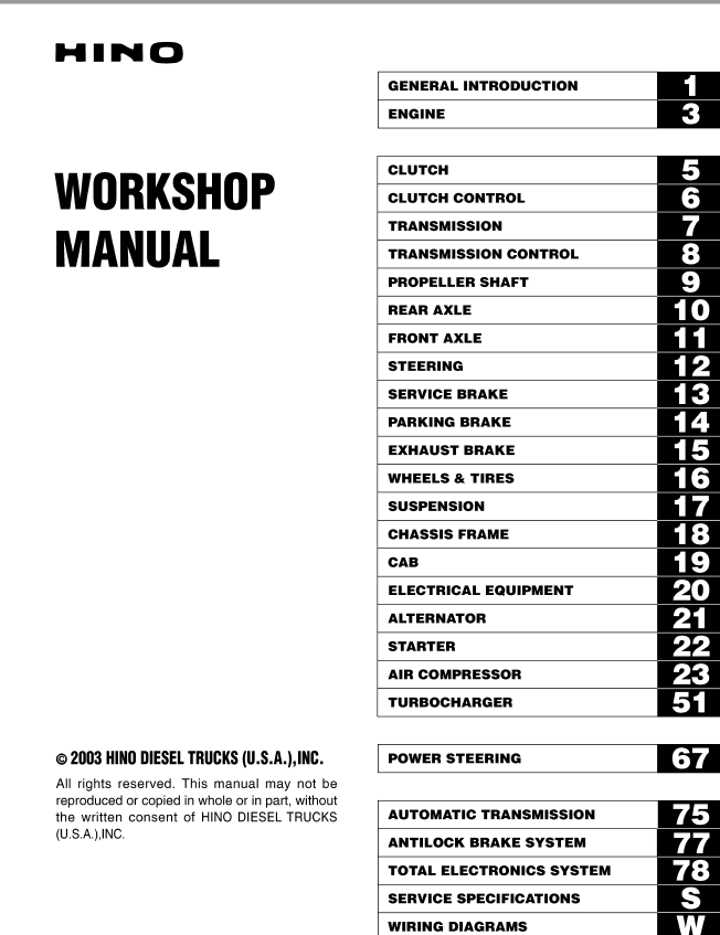
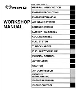
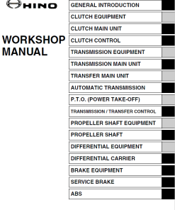
- General Introduction
- Engine
- Clutch and Clutch Control
- Transmission and Transmission Control
- Propeller Shaft
- Rear Axle and Front Axle
- Steering
- Service Brake, Parking Brake, and Exhaust Brake
- Wheels & Tires
- Suspension
- Chassis Frame and Cab
- Electrical Equipment, Alternator, Starter, and Compressor
- Turbocharger
- Spring Brake
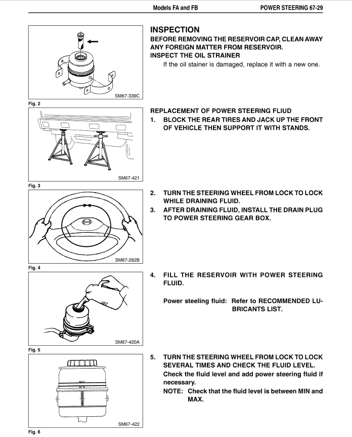
- Power Steering
- Automatic Transmission
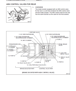
- Antilock Brake System
- Total Electronics System
- Service Specification
- Electrical Wiring Diagrams
Manual Instruction Extract
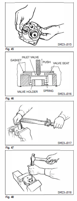
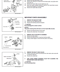
Assembly: Before assembling, ensure all sliding parts are lubricated with engine oil, and replace the O-rings and gaskets with new ones. Carefully follow the steps to assemble the inlet valve:
- Install the gasket, valve seat, inlet valve, and valve spring in sequence from the lower side of the cylinder head. Secure the valve holder loosely.
- Before tightening completely, press the inlet valve from the upper side using a finger or bar, ensuring the valve and spring operate smoothly.
- Tighten the valve holder to the specified torque using the special tool: Adapter (09481 – 1090), Tightening Torque: 1,000 – 1,200 kg-cm (73 – 86 lb-ft).
- Verify that the inlet valve stroke is approximately 2.5 mm (0.098 inches).
- Secure three areas around the outer periphery of the valve holder, ensuring the lower face of the valve holder is flush or recessed relative to the head lower face.
Only logged in customers who have purchased this product may leave a review.
Related products
$36.00
$36.00
$33.00
$36.00
$36.00
$33.00






Reviews
There are no reviews yet.