-
×
 Caterpillar CAT D6H Track Type Tractor Service Repair Manual (5HF00001 till 03999)
$70.00
Caterpillar CAT D6H Track Type Tractor Service Repair Manual (5HF00001 till 03999)
$70.00 -
×
 Caterpillar CAT CB-534D, CB-534DXW Vibratory Compactor Service Repair Manual (FEA00001 and up)
$50.00
Caterpillar CAT CB-534D, CB-534DXW Vibratory Compactor Service Repair Manual (FEA00001 and up)
$50.00 -
×
 New Holland W50C, W60C, W70C, W80C Stage 3B Loader Service Manual
$35.00
New Holland W50C, W60C, W70C, W80C Stage 3B Loader Service Manual
$35.00 -
×
 Komatsu WA470-6, WA480-6, WA470-6LC, WA480-6LC Loader Service Manual
$36.00
Komatsu WA470-6, WA480-6, WA470-6LC, WA480-6LC Loader Service Manual
$36.00 -
×
Caterpillar CAT D6M Track Type Tractor Service Repair Manual (4GS00001 and up)
$70.00
-
×
 Komatsu D355-A1 Dozer Service Manual
$29.00
Komatsu D355-A1 Dozer Service Manual
$29.00 -
×
 John Deere 3154G Swing Excavator Repair Technical Manual (S.N after F310001 - )
$59.00
John Deere 3154G Swing Excavator Repair Technical Manual (S.N after F310001 - )
$59.00 -
×
 New Holland G140VP, G170VP, G200 Motor Grader Service Manual
$34.00
New Holland G140VP, G170VP, G200 Motor Grader Service Manual
$34.00 -
×
 Timberjack 560, 660 Skidder Service Repair Manual
$39.00
Timberjack 560, 660 Skidder Service Repair Manual
$39.00 -
×
 JCB 2TFT, 2THS, 2TST, 3.5TST, 3TFT, 3TST Site Dumper Thwaites Service Manual
$35.00
JCB 2TFT, 2THS, 2TST, 3.5TST, 3TFT, 3TST Site Dumper Thwaites Service Manual
$35.00 -
×
 Timberjack 762C Harvester Head Service Repair Manual (SN 01FA1056 and up)
$29.00
Timberjack 762C Harvester Head Service Repair Manual (SN 01FA1056 and up)
$29.00 -
×
 Fiat 85-55, 95-55, 855C, 955C Tractor Service Manual
$26.00
Fiat 85-55, 95-55, 855C, 955C Tractor Service Manual
$26.00 -
×
 New Holland T4040, T4050 Tractor Service Manual
$34.00
New Holland T4040, T4050 Tractor Service Manual
$34.00 -
×
Caterpillar CAT D5H Track-Type Tractor Service Repair Manual (9HC00001 and up)
$70.00
-
×
 Liebherr L512, L514 Stereo Wheel Loader Service Manual
$35.00
Liebherr L512, L514 Stereo Wheel Loader Service Manual
$35.00 -
×
 Komatsu D375A-3 Dozer Service Manual
$35.00
Komatsu D375A-3 Dozer Service Manual
$35.00 -
×
 John Deere 953MH, 959MH Tracked Harvester Repair Manual (S.N C317982 - & D317982 - )
$57.00
John Deere 953MH, 959MH Tracked Harvester Repair Manual (S.N C317982 - & D317982 - )
$57.00 -
×
 John Deere 2654G, 2654GLC Swing Excavator Repair Manual (S.N C260001 - & D260001 - )
$57.00
John Deere 2654G, 2654GLC Swing Excavator Repair Manual (S.N C260001 - & D260001 - )
$57.00 -
×
 Kubota B2420 Tractor Service Manual
$33.00
Kubota B2420 Tractor Service Manual
$33.00 -
×
 New Holland LW270.B Wheel Loader Service Manual
$28.00
New Holland LW270.B Wheel Loader Service Manual
$28.00 -
×
 New Holland D180 LT, D180 XLT, D180 LGP Crawler Dozer Repair Service Manual
$32.00
New Holland D180 LT, D180 XLT, D180 LGP Crawler Dozer Repair Service Manual
$32.00 -
×
 New Holland TL70A, TL80A, TL90A, TL100A Tractor Service Manual
$36.00
New Holland TL70A, TL80A, TL90A, TL100A Tractor Service Manual
$36.00 -
×
Caterpillar CAT D3C Track-Type Tractor Service Repair Manual (5NS00001 and up)
$70.00
-
×
 Komatsu WA250-6, WA250PZ-6 Wheel Loader Service Manual
$35.00
Komatsu WA250-6, WA250PZ-6 Wheel Loader Service Manual
$35.00 -
×
 Case 821C Loader Service Manual
$34.00
Case 821C Loader Service Manual
$34.00 -
×
 New Holland L213, L215, L216 SkidSteer Loader Service Manual
$38.00
New Holland L213, L215, L216 SkidSteer Loader Service Manual
$38.00 -
×
Caterpillar CAT D6R Track Tractor Service Repair Manual (7GR00001 and up)
$70.00
-
×
Caterpillar CAT D6M Track-Type Tractor Service Repair Manual (5WR00001 and up)
$70.00
-
×
 Hitachi ZW220-5A, ZW220-5B Wheel Loader Service Repair Manual
$36.00
Hitachi ZW220-5A, ZW220-5B Wheel Loader Service Repair Manual
$36.00 -
×
 John Deere E380LC, E400LC Excavator Repair Manual (S.N after CXXXXXX - & DXXXXXX -)
$51.00
John Deere E380LC, E400LC Excavator Repair Manual (S.N after CXXXXXX - & DXXXXXX -)
$51.00 -
×
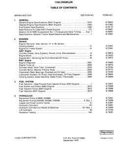 Case 1150 Crawler Dozer Service Manual
$34.00
Case 1150 Crawler Dozer Service Manual
$34.00
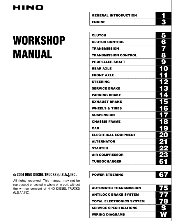
Hino Truck FA4J, FB4J Year 2004 Repair and Service Manual
Product Overview
This comprehensive repair and service manual is tailored for the Hino Truck Series of 2004, including models FA, FB, FD, FE, and SG. It is available in a convenient PDF format and is written in English. With a total of 1104 pages, this manual provides detailed insights into the repair processes for Hino 2004 trucks, specifically for the FA and FB series.
Key Features
- Format: PDF
- Language: English
- Comprehensive coverage across 1104 pages
- Applicable to Hino 2004 FA and FB truck series
Benefits
- Ensures smooth, safe, and economical operation of your Hino truck.
- Highlights the importance of regular inspections and maintenance.
- Detailed instructions to prevent injuries during repair procedures.
- Includes the latest product information available at the time of printing.
Usage Recommendations
- Owners are responsible for performing necessary maintenance as outlined in this manual and the Owner’s Manual.
- Refer to the Owners and Drivers Manual for maintenance item specifics.
- Follow recommended repair guidelines to ensure optimal vehicle performance.
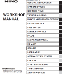
Table of Contents
- General Introduction
- Engine
- Clutch
- Clutch Control
- Transmission
- Transmission Control
- Propeller Shaft
- Rear Axle
- Front Axle
- Steering
- Service Brake
- Parking Brake
- Exhaust Brake
- Wheels & Tires
- Suspension
- Chassis Frame
- Cab
- Electrical Equipment
- Alternator
- Starter
- Compressor
- Turbocharger
- Spring Brake
- Power Steering
- Automatic Transmission
- Antilock Brake System
- Total Electronics System
- Service Specification
- Electrical Wiring Diagrams
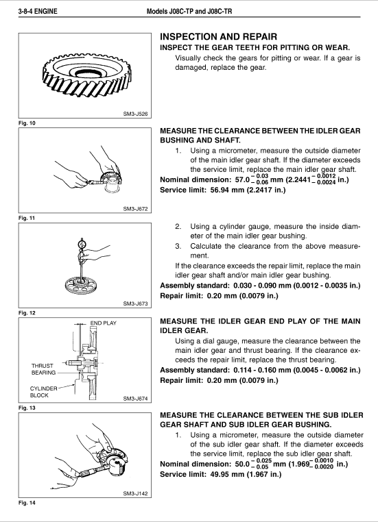
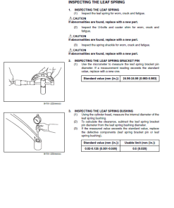
Extract from the Manual: Inspection
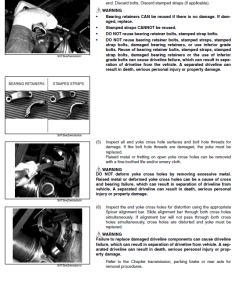
nINSPECTION
1. Check the operation of the engine stop motor and mechanical switch. When removing the engine stop cover, do not touch the cable or pulley. Ensure the key switch is in “ACC” or “OFF” positions, and only check the motor after disconnecting the battery.
- Devise a circuit as instructed in Fig. 8.
- Power the switch to rotate the motor, confirming it stops where the cable spring moves to the “in use” position.
- If the motor and switch operate correctly, the motor will stop where the cable spring moves to the “stop” position.
2. If the engine does not stop with the starter switch in “OFF”, follow these steps:
- Switch the starter to “ON”.
- Open the front panel.
- Disconnect the engine stop motor connector.
- Remove the engine stop motor cover.
- Pull the engine stop cable as indicated to stop the engine.
- After stopping, replace the motor cover.
- Reconnect the motor connector.
- Switch the starter to “LOCK”.
Only logged in customers who have purchased this product may leave a review.
Related products
$36.00
$36.00
$36.00

$36.00
$36.00

$36.00
Reviews
There are no reviews yet.