-
×
 Yale ERP040DH, ERP050DH, ERP060DH Forklift D216 Series Repair Manual
$34.00
 -
×
 Hitachi ZH200-5A and ZH200LC-5A Excavator Service Repair Manual
$40.00
 -
×
 John Deere 4200, 4300, 4400 Compact Utility Tractors Technical Manual
$38.00
 -
×
 JCB JCB305, JS305 Excavator Service Repair Manual
$36.00
 -
×
 Caterpillar CAT 257B2 Multi Terrain Loader Service Repair Manual (SLK07300 and up)
$70.00
 -
×
 Yale ESC020AB, ESC025AB, ESC030AB Forklift A824 Service Repair Manual
$25.00
 -
×
 Caterpillar CAT 420F2 Backhoe Loader Service Repair Manual (LYB00001 and up)
$70.00
 -
×
 John Deere STX30, STX38, STX46 Lawn Tractors Technical Manual
$29.00
 -
×
 Yale GDP40VX5, GDP40VX6, GDP45VX6, GDP50VX, GDP55VX Forklift H813 Series Repair Manual
$38.00
 -
×
 Yale GDP130EC, GDP140EC, GDP160EC Forklift G877 Series Repair Manual
$35.00
 -
×
 Yale GLP40VX5, GLP40VX6, GLP45VX6, GLP50VX, GLP55VX Forklift J813 Series Repair Manual
$38.00
 -
×
 John Deere 6200, 6200L, 6300, 6300L, 6400, 6400L, 6500, 6500L Tractors Repair Manual
$70.00
 -
×
 JCB 435 Wheeled Loader Shovel Service Manual
$34.00
 -
×
 CNH VM Motori R 753 IE4 Tier 4B and Stage IV Engine Service Manual
$33.00
 -
×
 Bobcat 130 Hydraulic Excavator Service Manual
$29.00
 -
×
 Caterpillar CAT 426C Backhoe Loader Service Repair Manual (1CR00864 till 01085)
$70.00
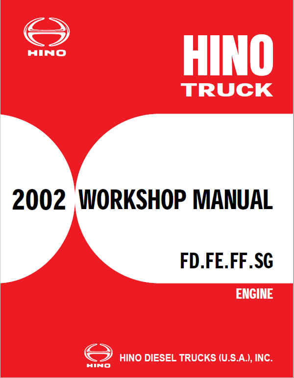
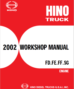
Hino Truck FD2J, FE2J, FF2J, SG1J, SG2J Year 2002 Repair Manual (FD, FE, FF, SG)
$36.00
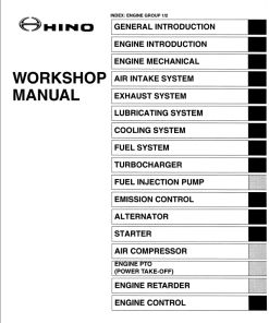
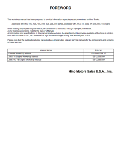
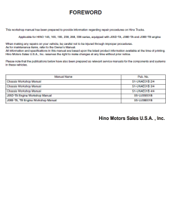
Access the comprehensive Hino Truck 2002 Repair and Service Manual for FD, FE, FF, and SG Series models. This vital resource is provided in a convenient PDF format and is available in English.
Key manuals included:
SKU: 718463
Category: Hino
Hino Truck FD2J, FE2J, FF2J, SG1J, SG2J 2002 Repair Manual
Product Overview
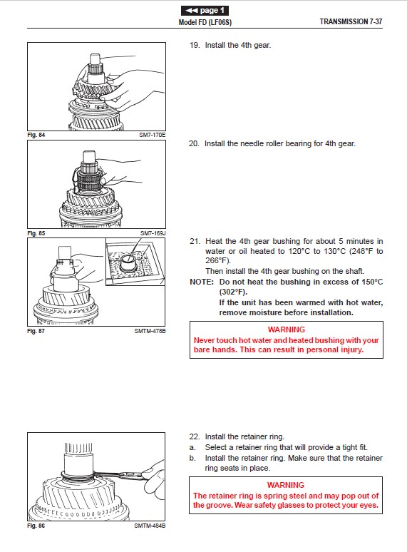
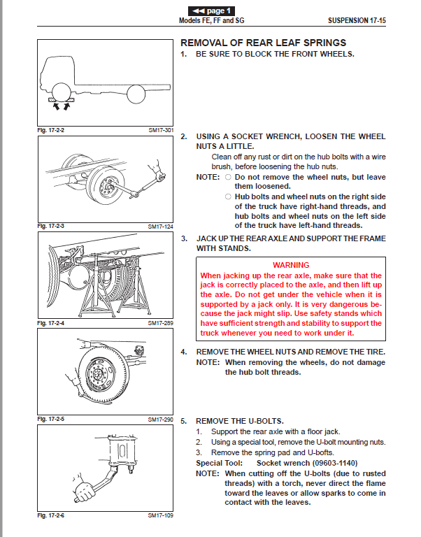
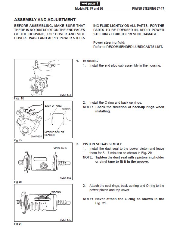
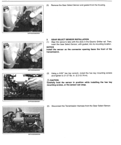
This comprehensive repair and service manual is specifically designed for the 2002 Hino Truck series, including models FD, FE, FF, and SG. Available in PDF format, this manual is written in English and contains detailed instructions for maintaining and repairing your Hino truck to ensure longevity and optimal performance.
Download the manual from The Repair Manual website.
Key Features
- Extensive Coverage: 1528 pages dedicated to Hino 2002 Truck FD, FE, FF, SG Series.
- Engine Specific Manuals:
- Hino J05D-TA Engine Manual – 324 pages
- Hino J08E-TA & J08E-TB Engine Manual – 351 pages
- Complete Repair Instructions: Detailed guidance on everything from basic maintenance to complex repairs.
Benefits
- Enhanced Truck Performance: Keep your truck running smoothly and economically with proper maintenance.
- Safety Assurance: Follow recommended inspection schedules to ensure your vehicle operates safely without unexpected issues.
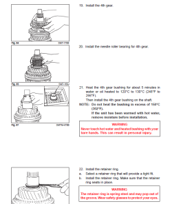
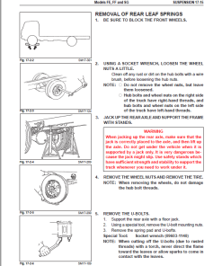
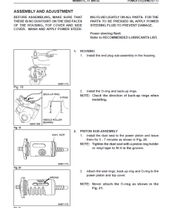
- Detailed Repair Guidance: Step-by-step instructions help avoid injury and ensure correct repairs.
Usage Recommendations
- Regularly consult the manual for routine maintenance tasks to ensure truck safety and efficiency.
- Follow the detailed instructions for any repairs to prevent damage or injury.
- Reference the Owners and Drivers Manual for additional maintenance guidelines.
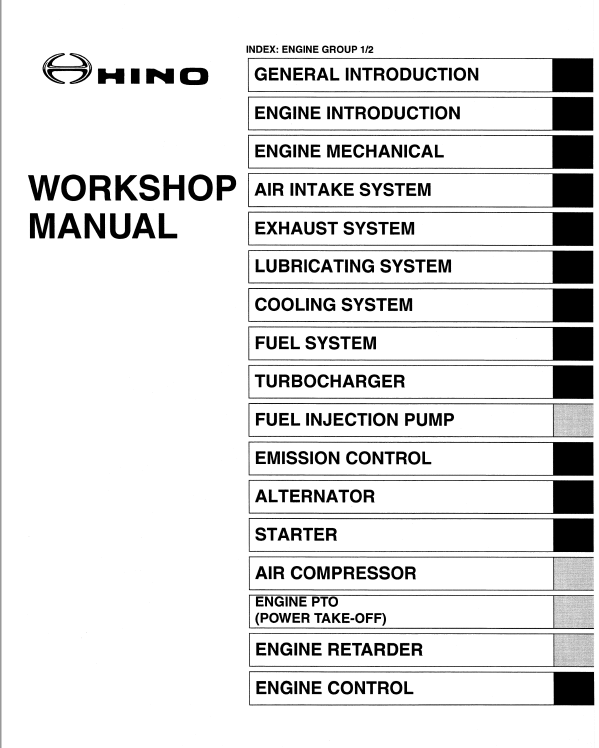
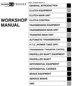
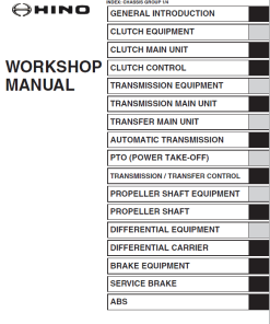
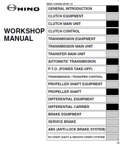
Table of Contents
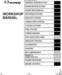
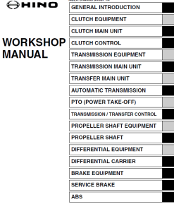
- General Introduction
- Engine
- Clutch and Clutch Control
- Transmission and Transmission Control
- Propeller Shaft
- Rear and Front Axle
- Steering
- Service, Parking, and Exhaust Brake
- Wheels & Tires
- Suspension
- Chassis Frame
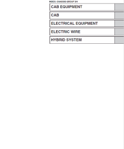
- Cab
- Electrical Equipment, Alternator, and Starter
- Compressor and Turbocharger
- Spring Brake and Power Steering
- Automatic Transmission
- Antilock Brake System
- Total Electronics System
- Service Specification
- Electrical Wiring Diagrams
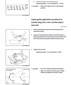
Instruction Extract: Valve Clearance Checking and Adjusting Procedures
n
Ensure that essential components such as the cylinder head bolts, rocker support, nozzle clamp, cam housing, and cam bearing cap are tightened to the specified torque before starting this procedure.
Follow these steps for accurate valve clearance adjustment:
- Remove any foreign particles or dust between the cross head and valve stem.
- Align the No. 1 piston to the top dead center of the compression stroke by turning the crankshaft forward.
- Check that the roller is on the base circle of the camshaft.
- Insert a feeler gauge between the rocker arm and the cross head to check valve clearance.
- If adjustment is needed, follow the detailed steps ensuring correct torque settings and feel for the gauge.
Standard Valve Clearance (when cold):
- Intake valve: 0.30mm (0.0118 in.)
- Exhaust valve: 0.45mm (0.0177 in.)
“, “
Only logged in customers who have purchased this product may leave a review.
Related products
$36.00
$33.00
$33.00
$36.00



Reviews
There are no reviews yet.