 Komatsu PC1250-8, PC1250SP-8, PC1250LC-8 Excavator Service Manual
  Komatsu PW75R-2 Excavator Service Manual
  Komatsu PC400-7E0, PC400LC-7E0, PC450-7E0, PC450LC-7E0 Excavator Manual

Komatsu PC15MR-1 Excavator Service Manual
Product Overview
The Komatsu PC15MR-1 Excavator Service Manual is an essential guide for owners and technicians working with the PC15MR-1 excavator model. This comprehensive manual provides detailed instructions and specifications to assist with the maintenance, repair, and optimal performance of your equipment.
Key Features
- General Information: Covers machine dimensions, performance specifications, component weights, and charts for fuel, coolant, and lubricant specifications.
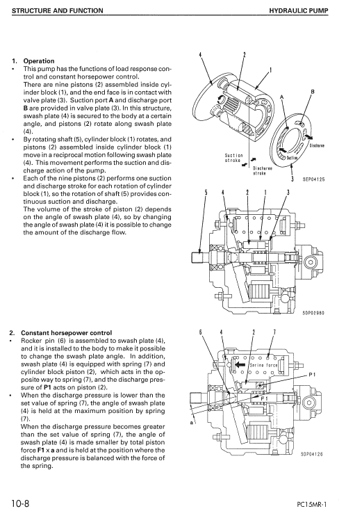
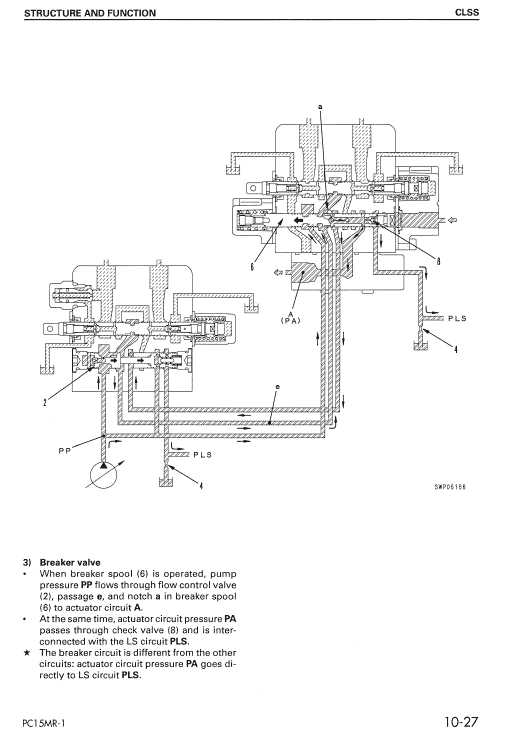
- Structure and Function: Offers in-depth insights into the structure and function of each component, acting as a reference for troubleshooting.
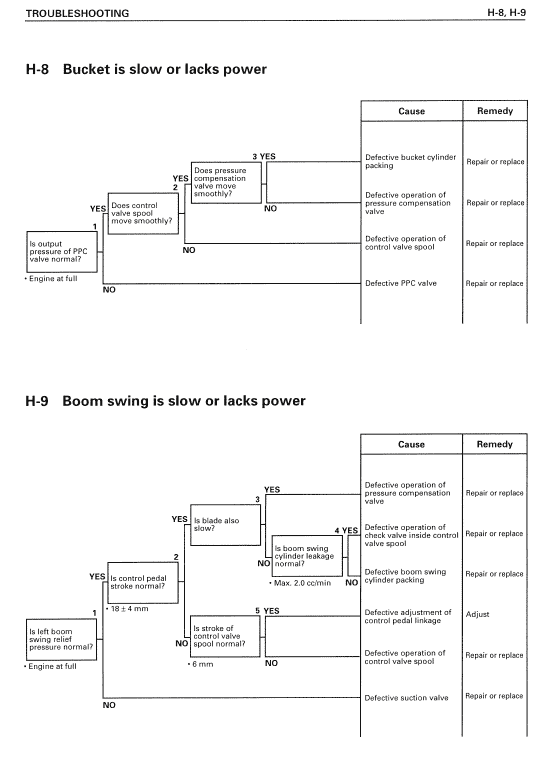
- Testing and Adjusting: Details essential checks to be made before and after repairs, includes adjustments to ensure proper functioning, and provides troubleshooting charts.
- Disassembly and Assembly: Provides a step-by-step guide for removing, installing, disassembling, and assembling components, including necessary precautions.
- Adjusting Valve Clearance: Instructions for adjusting valve clearance to ensure the engine operates smoothly.
Benefits
- Ensures precise and efficient maintenance of the PC15MR-1 excavator.
- Helps identify and troubleshoot issues promptly, minimizing downtime.
- Guides on safe and proper assembly and disassembly, preserving the longevity of components.
- Facilitates optimal engine performance through correct valve adjustments.
Usage Recommendations
- Use this manual to perform routine checks and maintenance to prolong the life of your excavator.
- Follow the troubleshooting section to address any operational problems swiftly.
- Refer to the assembly section when replacing or installing parts to ensure proper techniques are used.
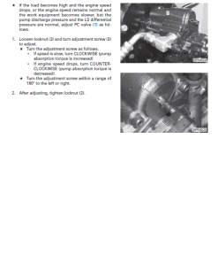
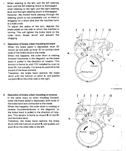
Adjusting Valve Clearance Procedure
n
- Remove the air cleaner (1) and the cylinder head cover. Additionally, remove the air cleaner bracket.
- Detach cap (2) from the flywheel housing.
- Rotate the crankshaft in the normal direction to align the No. 1 line b on the flywheel with line a on the housing. Ensure the valves of the No. 1 cylinder (flywheel end) are checked for movement.
- Continue rotating the crankshaft 240 degrees with each adjustment, following the firing order of 1-3-2. Adjust the valve clearance for each cylinder at its top dead center.
- To adjust the valve clearance, use a feeler gauge E between the rocker lever (3) and the valve stem (4), adjusting screw (5) until the clearance fits snugly. Secure the adjustment by tightening locknut (6).
- Ensure that the locknut is tightened to 25.5 u00b1 2.9 Nm (2.6 u00b1 0.3 kgm), and recheck the clearance after tightening.
Only logged in customers who have purchased this product may leave a review.
Related products
$32.50
$27.50
$33.00
Reviews
There are no reviews yet.