HST Controller Gear Shift Display Manual
Product Overview
This manual provides comprehensive guidance on the gear shifting display function of the HST controller used in heavy machinery. It details how input signals related to gear shifts are displayed on the machine monitor, aiding in the operational efficiency and safety of the machinery.
Table of Contents
- General
- Structure and Functions
- Testing and Adjusting
- Disassembly and Assembly
- Maintenance Standard
- Others
Key Features
- Directional Indicators: Displays the state of the directional lever position on the machine monitor using pilot lamps. When the directional lever is in neutral, all position lamps turn off. Incorrect input signals may illuminate multiple lamps simultaneously.
- Reverse Functionality: Activates backup lamp relay and sounds a back-up alarm when the directional lever is set to “R (reverse).”
- Speed Range Indicator: Shows the position of the travel speed range selector switch on the monitor.
- Variable Shift Control System: Allows for adjusting the maximum speed in the range of 4 – 13 km when set to the 1st speed.
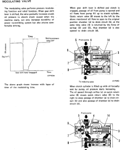
- Transfer Clutch Control Function: Optimizes clutch oil pressure to reduce impacts and prevent torque deficiencies by considering various machine state parameters such as speed and load.
Benefits
- Improves machine operation precision through clear visual indicators.
- Enhances safety by providing reliable directional and speed indications.
- Ensures smooth clutch engagement, reducing mechanical impact.
- Facilitates maintenance and troubleshooting via an organized manual structure.
Usage Recommendations
- Ensure all operators are trained to interpret the gear shift display correctly.
- Regularly test the system to confirm all indicators and functions are operational.
- Immediately address any discrepancies or malfunctions in indicator signals to prevent operational errors.
- Refer to the modulation table in the HST controller as needed for optimal performance adjustments.
Only logged in customers who have purchased this product may leave a review.
Related products
$33.50
$33.50
$27.50
$33.00

 Bobcat 3400, 3400XL Utility Vehicle Service Repair Manual
 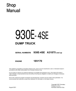 Komatsu 930E-4SE Dump Truck Service Repair Manual
 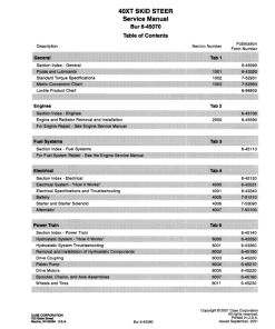 Case 40XT SkidSteer Service Manual

Reviews
There are no reviews yet.