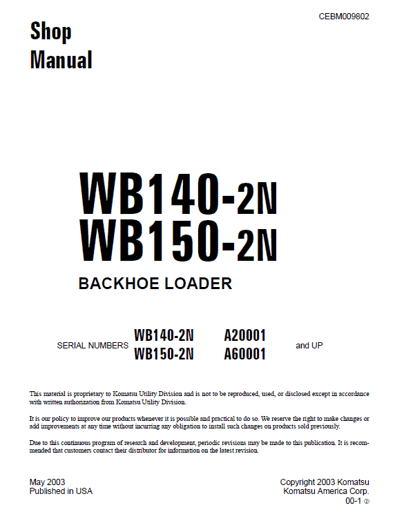
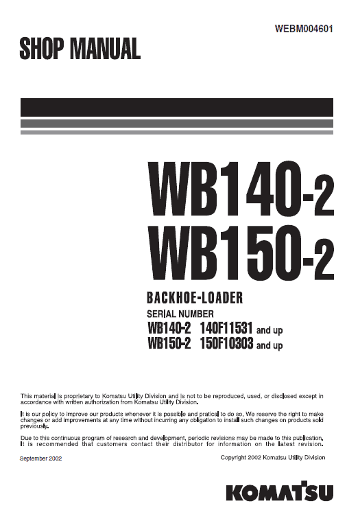
Komatsu WB140-2 and WB150-2 Backhoe Loader Service Manual
Product Overview
This comprehensive service manual provides detailed information and procedures for the maintenance and repair of the Komatsu WB140-2 and WB150-2 Backhoe Loaders. Aimed at service professionals, it ensures familiarity with the equipment’s functionality, supporting efficient troubleshooting, testing, disassembly, and assembly.
Table of Contents
- Structure and Function
- Testing and Adjusting
- Disassembly and Assembly
- Maintenance Standard
General Instructions
Gain a foundational understanding of the procedures encompassing disassembly, testing, troubleshooting, and installation. It is crucial for service personnel to internalize these instructions as part of their standard practices.
Structure and Function
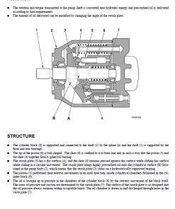
This section elaborates on the equipment’s structure, complete with detailed drawings of constituent components, and provides block or circuit diagrams for clarity. These resources serve not only as guides but also as educational tools for training service personnel.
Testing and Adjustments
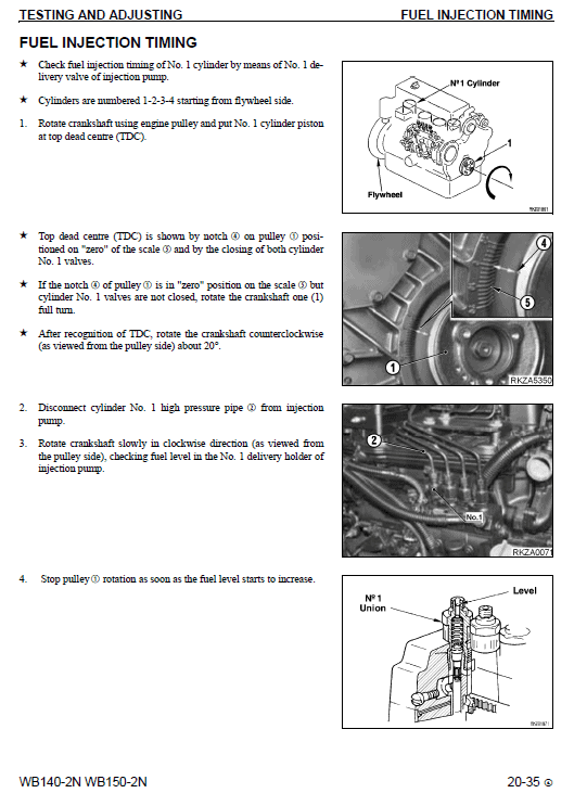
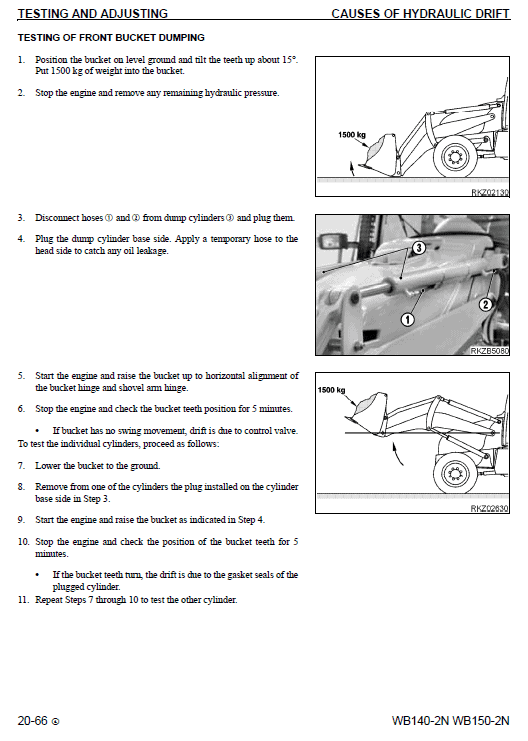
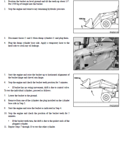
All necessary tests and adjustments are thoroughly described, with accompanying photographs illustrating the measuring equipment and specific measurement locations. This aids technicians in troubleshooting, inspecting, and calibrating the machinery.
Troubleshooting
Find common issues, their causes, and diagnostic procedures systematically detailed. For atypical problems, technicians should refer to the “Structure and Function” and “Testing and Adjustments” sections to apply learned diagnostic techniques.
Specifications
The manual details all standard dimensions and tolerances crucial for testing, adjustments, repairs, and troubleshooting. Focused on commonly serviced machine parts, it guides through procedures for disassembly, assembly, and repair.
Removal of Steering Unit
n
To remove the steering unit, lower the working equipment completely to the ground, stop the engine, and remove the ignition key. Follow these steps:
- Release all residual pressure in the circuits (refer to “Testing and Adjustments” for details).
- Turn the accumulator disconnect switch counterclockwise to cut off electricity and remove the handle.
- Disconnect the five pipes from the steering unit and seal them to prevent contamination. Mark positions for correct reconnection.
- Remove the central guard beneath the steering wheel.
- Lift the protective sleeve and disconnect the connectors.
- Disconnect the additional connectors and relay.
- Loosen the retaining screws on the steering column and steering unit, then remove the steering unit.
Only logged in customers who have purchased this product may leave a review.









Reviews
There are no reviews yet.