-
×
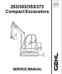 Gehl GE 253, GE 303, GE 353, GE 373 Excavator Repair Service Manual
$36.00
 -
×
 Komatsu WB146PS-5 Backhoe Loader Service Manual
$34.00
 -
×
 Komatsu D31E-20, D31P-20, D31PL-20, D31PLL-20 Dozer Manual
$34.00
 -
×
 AGCO Sisu 320, 420, 620, 634 Engines Workshop Repair Service Manual
$31.00
 -
×
 Massey Ferguson 2705E, 2706E Tractor Service Manual
$35.00
 -
×
 Massey Ferguson 2604H, 2605H, 2606H, 2607H Tractor Service Manual
$34.00
 -
×
 Massey Ferguson 6715S, 6716S, 6718S Tractor Service Manual
$37.00
 -
×
 Liebherr LH40C, LH40M, LH50M, LH50MT Tier 4F Excavator Service Manual
$35.00
 -
×
 Liebherr A910, A912, A914, A918 Tier 4F Compact Excavator Service Manual
$34.00
 -
×
 New Holland T1560, T1570 Tractors Service Manual
$32.00
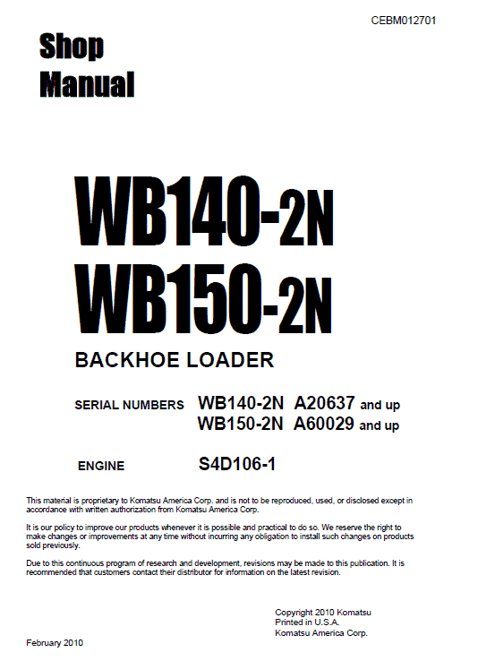
Komatsu WB140-2N and WB150-2N Backhoe Loader Service Manual
$34.50
Enhance your maintenance capabilities with the Komatsu Backhoe Loader Shop Manual, a comprehensive guide designed for the Komatsu models WB140-2N and WB150-2N. This manual, presented in English, contains 660 pages of detailed information.
Detailed Product Manual
Product Overview
This comprehensive manual provides in-depth information on machine dimensions, performance specifications, and essential guidelines for operating and maintaining machinery components effectively. It serves as a critical resource for understanding the various structural and functional aspects of the device as well as for conducting maintenance and troubleshooting activities.
Table of Contents
- General – 01-1
- Structure, Function, and Maintenance Standard – 10-1
- Testing, Adjusting, and Troubleshooting – 20-1
- Disassembly and Assembly – 30-1
- Other – 90-1
Section Details
General
This section provides detailed dimensions of the machine, performance specifications, and comprehensive charts for fuel, coolant, and lubricant specifications. Understanding these parameters is essential for optimal machine operation and maintenance.
Structure, Function and Maintenance Standard
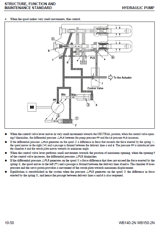
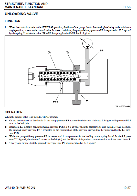
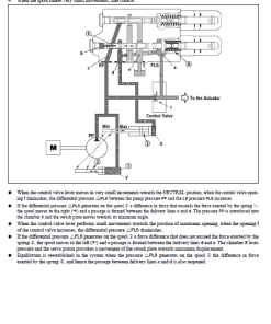
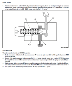
In this section, the structure and function of each component are explained in detail. It not only enhances understanding of the mechanical components but also acts as a vital reference for troubleshooting procedures.
Testing, Adjusting, and Troubleshooting
This section outlines pre- and post-repair checks and adjustments needed after repairs. It includes troubleshooting charts linking specific problems to their causes, ensuring efficient and effective resolution of issues.
Disassembly and Assembly
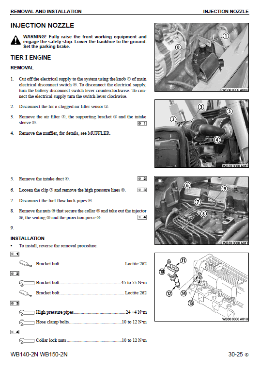
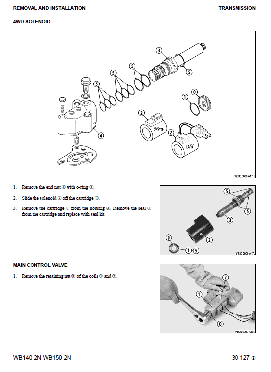
Guidelines for the correct order of removal, installation, disassembly, and assembly of components are given here. It highlights necessary precautions, especially for components under internal or spring pressure. Always keep two bolts in opposite positions until pressure is released, then carefully remove the rest.
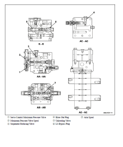
Flow Valve Testing
- Disconnect the hose from the load sensing line. Install the tee and reconnect the hose.
- Connect a pressure port and a gauge to the tee.
- Attach a second gauge to the control valve pressure port.
- With the engine running at low idle and no machine movement, check the pressure on both gauges.
- P Pressure at control valve gauge: 30 u00b1 3 kg/cm; Normal PLS pressure: 6 u00b1 2 kg/cm. Allowance for counter pressure in the steering circuit.
- If deviations are found, ensure that the difference does not exceed 21 u00b1 1 kg/cm. If it exceeds 24 u00b1 1 kg/cm, stop the engine and release residual pressures.
- Clean the valve thoroughly and reinstall it. Ensure a torque of 20 Nu00b7m.
- If the valve’s pressures remain out of tolerance after cleaning, replace the valve.
This manual offers meticulous procedures that ensure safe operation and minimize downtime. Following these guidelines ensures peak performance and longevity of machinery components.
Only logged in customers who have purchased this product may leave a review.
Related products
$32.50
$34.00
$33.50
$34.00





Reviews
There are no reviews yet.