-
×
 Caterpillar CAT 3208 Generator Set Engine Service Repair Manual (2HG00001 and up)
$50.00
 -
×
 Still EXG10, EXG12, EXG16 Pallet Stacker Workshop Repair Manual
$26.00
 -
×
 Caterpillar CAT 3054 Engine Machine Service Repair Manual (9RM00001 and up)
$45.00
 -
×
 Caterpillar CAT 3516B Marine Engine Service Repair Manual (S2Y00001 and up)
$45.00
 -
×
 Caterpillar CAT 3406 Engine Machine Service Repair Manual (11N00001 and up)
$45.00
 -
×
 Caterpillar CAT 3114 Generator Set Engine Service Repair Manual (5JG00001 and up)
$50.00
 -
×
 Caterpillar CAT 3046 Engine Machine Service Repair Manual (MHK00001 and up)
$45.00
 -
×
 Still MX15-3 Order Picker Workshop Repair Manual
$25.00
 -
×
 Still FM Type 429 and Type 447 Reach Truck Workshop Repair Manual
$26.00
 -
×
 Still FM-4W 20 and FM-4W 25 Reach Truck Workshop Repair Manual
$32.00
 -
×
 Caterpillar CAT 3306 Engine Machine Service Repair Manual (64Z00001 and up)
$45.00
 -
×
 Caterpillar CAT 3116 Engine Machine Service Repair Manual (3EJ00001 and up)
$50.00
 -
×
 Caterpillar CAT 3056 Generator Set Engine Service Repair Manual (7AK00001 and up)
$50.00
 -
×
 Caterpillar CAT 3126 Engine Machine Service Repair Manual (55K00001 and up)
$45.00
Massey Ferguson 1429, 1433, 1440 Tractor Service Manual
$33.00
Enhance your maintenance and repair skills with the Massey Ferguson 1429, 1433, 1440 Tractors Workshop Manual. This comprehensive guide features:
- Complete coverage in 320 pages and 308 pages
- Additional 124 pages on Iseki Three-Cylinder Diesel Engine (pre-2005 models)
Available in PDF format, this workshop manual is an essential resource for detailed mechanical insights.
Publication Numbers: 1449598M1 & 1449564M1
SKU: 363738
Categories: Massey Ferguson, Tractor
Massey Ferguson 1429, 1433, 1440 Tractor Workshop Manual
Product Overview
Enhance your understanding of Massey Ferguson tractors with the comprehensive workshop manual covering models 1429, 1433, and 1440. Designed for tractors featuring the Iseki three-cylinder diesel engine produced before 2005, this manual provides detailed instructions and technical information essential for maintenance and repair.
Format: PDF
Type: Workshop Manual
Publication Numbers: 1449598M1 & 1449564M1
Pages: 320 & 308
Engine Manual Pages: 124
Key Features
- Covers Massey Ferguson models 1429, 1433, and 1440.
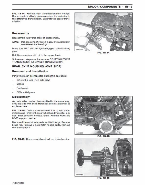
- Includes detailed technical specifications and diagrams.
- Easy-to-follow instructions for DIY enthusiasts and professionals.
- Extensive coverage of the Iseki three-cylinder diesel engine.
Benefits
- Provides in-depth knowledge to perform repairs efficiently.
- Helps extend the lifespan and performance of your tractor.
- Empowers users to conduct routine maintenance independently.
- Offers cost-saving opportunities by reducing dependence on professional services.
Usage Recommendations
- Suitable for owners and operators of Massey Ferguson 1429, 1433, and 1440 models.
- A valuable resource for service technicians and mechanics.
- Ideal for use in agricultural settings requiring regular upkeep.
- Consult relevant sections for troubleshooting and repair guidance.
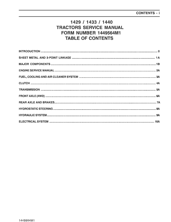
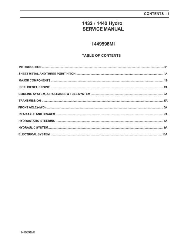
Manual Table of Content
INTRODUCTION …………………………………………………………………………. 01
SHEET METAL AND THREE POINT HITCH ………………………………… 1A
MAJOR COMPONENTS ………………………………………………………………. 18
ISEKI DIESEL ENGINE …………………………………………………………….. 2A
COOLING SYSTEM, AIR CLEANER & FUEL SYSTEM …………………….. 3A
TRANSMISSION ………………………………………………………………………… 5A
FRONT AXLE (4WD) ………………………………………………………………….. 6A
REAR AXLE AND BRAKES ………………………………………………………….. 7A
HYDROSTATIC STEERING …………………………………………………………… 8A
HYDRAULIC SYSTEM …………………………………………………………………. 9A
ELECTRICAL SYSTEM ……………………………………………………………… 10A
PTO Clutch
The PTO is driven through a wet, multi-disc, hydraulically operated clutch pack. To engage PTO, ensure the mechanical PTO lever on the left-hand side of the tractor is engaged, and the on/off switch on the console is in the u201cONu201d position. Activating the switch energizes the PTO valve, allowing oil pressure to clamp the discs together, thus turning the PTO shaft.
Oil Supply to PTO Clutch Pack
Oil is directed from the main hydraulic pump to a reducing valve, acting as a flow divider. The reducing valve splits the flow into primary and secondary circuits. The PTO clutch pack receives oil from the secondary circuit, with maintained line pressure to ensure optimal operation. For further details on the reducing valve, refer to the Hydraulic System section.
For more information, visit the Massey Ferguson section on our website.
Only logged in customers who have purchased this product may leave a review.
Related products
Massey Ferguson
$36.50
Massey Ferguson
$34.00
$27.00 – $38.00
Massey Ferguson
$36.00
Massey Ferguson
$10.00 – $37.00
Massey Ferguson
Massey Ferguson MF3600 V – S – F – GE Series Workshop Manual
$41.00
Massey Ferguson
Massey Ferguson 3615, 3625, 3635, 3645 Workshop Service Manual
$19.00 – $36.00
Massey Ferguson
$34.00

Reviews
There are no reviews yet.