-
×
 Massey Ferguson MF165 Tractor Service Manual
$30.00
 -
×
 Massey Ferguson MF 9205 Telescopic Handler Service Manual
$34.00
 -
×
 Massey Ferguson 3050, 3060, 3065, 3070, 3080 Tractor Service Manual
$34.00
 -
×
 Gehl AL 650 Articulated Loader Repair Service Manual
$36.00
 -
×
 John Deere 1050K Crawler Dozer Technical Manual (SN. from C268234 - C318801)
$59.00
Massey Ferguson 2605, 2615 Tractor Service Manual
$35.00
SKU: 783787
Categories: Massey Ferguson, Tractor
Massey Ferguson 2605, 2615 Tractor Service Manual
Product Overview
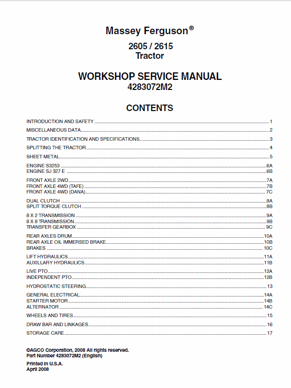
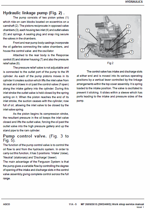
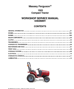
This comprehensive workshop service manual for Massey Ferguson models 2605 and 2615 provides essential information for service technicians. Available in PDF format, it serves as an invaluable tool for the maintenance and repair of these tractors, equipping users with critical guidelines and technical support.
To view the manual, visit the official page. This manual, with Publication No: 4283072M2, is meticulously designed to assist users in navigating service procedures with confidence.
Key Features
- Detailed Workshop Manual – 673 Pages
- Parts Catalog Manual – 75 Pages & 78 Pages
- Includes procedure for eliminating air from the fuel system with SJ327E and VE type fuel pump.
Benefits
- Provides the latest service information for effective maintenance and repairs.
- Helps prevent potential service errors by guiding through step-by-step procedures.
- Facilitates familiarization with critical components and service steps for efficient troubleshooting.
Usage Recommendations
- Read the service manual thoroughly before initiating any repair work on the tractors.
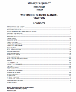
- Use the Table of Contents to quickly locate necessary information like maintenance schedules and specifications.
Sample Procedure: Eliminating Air from Fuel System (SJ327E with VE Type Fuel Pump)
This section explains how to remove air from the fuel line system using the SJ327E engine equipped with a MICO VE-type fuel injection pump:
- Ensure diesel fuel flows freely to the feed pump inlet and tighten the banjo bolt.
- Utilize the hand primer to release air:
- At the vent screw of the primary fuel filter bowl. Tighten the vent screw when fuel flows without air.
- At the vent screw of the secondary fuel filter bowl. Tighten the vent screw when fuel flows without air.
- At the overflow banjo bolt (marked OUT) on the fuel injection pump. Tighten once air is expelled.
- Loosen the three nuts on the high-pressure fuel pipe at the atomizer and crank the engine until air-free fuel flows.
- Tighten the nuts on the high-pressure pipe at the atomizer. The engine is ready to start.
7B – 12 Differential Carrier Assembly: Removal and Refitment
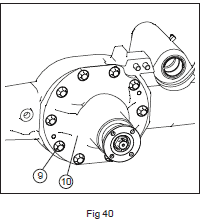
Removal
- Apply the parking brake to secure the tractor.
- Jack up the front and support under the engine.
- Slide back the propeller shaft guard and disconnect the shaft.
- Remove the axle following operation 7B – 5.
- Detach both front wheels.
- Drain oil from the axle housing.
- Remove swivel housings as per operation 7B – 9 without dismantling the hubs.
- Detach the steering ram as outlined in operation 7B – 16.
- Unscrew the ten bolts fixing the differential carrier to the axle casing. Handle with care due to its weight.
- Gently pry the differential from the axle, supporting its weight throughout.
Refitment
Reverse steps 1 to 10. Key exceptions include:
- Apply Massey Ferguson Instant Gasket (Loctite 596) on the differential case joint face.
- Apply Loctite 118 to differential carrier bolts, tightening to 95 – 103 lbf.ft (130 – 140 Nm).
Table of Contents Highlights
Explore detailed sections such as:
- “, “
Only logged in customers who have purchased this product may leave a review.
Related products
Massey Ferguson
Massey Ferguson GC1705, GC1710, GC1715, GC1720 Service Manual
$25.00 – $34.00
$20.00 – $38.00
Massey Ferguson
$34.00
Massey Ferguson
$10.00 – $37.00
$34.00
$30.00
Massey Ferguson
$36.50
Massey Ferguson
$36.00



Reviews
There are no reviews yet.